
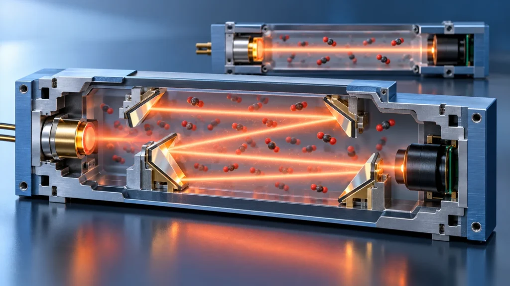
Các optical path length of an NDIR CO₂ sensor is the distance over which the infrared beam interacts with the gas. It influences how much light CO₂ absorbs before the detector measures what remains. Longer interaction can make a small concentration change more visible, but it can also leave too little transmitted light at high concentrations. The right length depends on the intended range, optical power, noise, calibration and packaging.
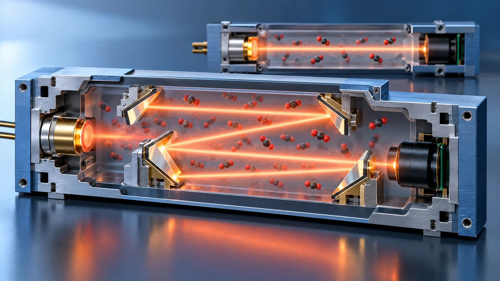
Path length is not the same as the outside length of a sensor module or the volume of its gas cavity. A folded optical path can fit a longer interaction into a compact housing. Conversely, a large-looking enclosure may contain a short effective beam path. Those distinctions matter when selecting a module for room air, greenhouse control, a process sample or a compact monitor.

Why Does Path Length Change the Signal?
For a simplified single-wavelength measurement, the Beer–Lambert model describes transmission as T = I/I₀ = e^(−εcL). Here c is concentration and L is optical interaction length. At the same concentration and absorption behavior, increasing L reduces transmitted intensity. Hamamatsu's NDIR design article uses this relationship to explain a gas cell, light emitter and detector.
This model is useful for direction, not for predicting a complete instrument's accuracy from a ruler. Real NDIR channels measure a band of wavelengths through filters; the source spectrum, detector sensitivity, optical losses, gas pressure, temperature and calibration model affect the response. The apparent response is generally not a simple linear fall in detector voltage with CO₂ concentration.
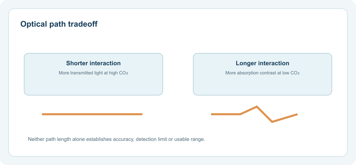
At low concentration, a short path may yield only a small difference from a baseline signal. At high concentration, a long path may absorb so much light that the detector has little signal to work with. Between those limits lies a range where the design can resolve useful changes with an acceptable noise and error budget.

The Low-Concentration and High-Concentration Tradeoff
Imagine two otherwise identical optical systems with different path lengths. The longer path generally gives more absorption for a small CO₂ fraction, potentially improving sensitivity to small changes. That benefit is conditional: mirrors, windows and extra distance also lose light, and a weaker detector signal can increase noise. Improved absorption contrast does not prove improved accuracy unless the whole design is tested and calibrated.
At percentage-level CO₂, an optical design optimized for modest indoor changes may approach a weak transmitted signal or a model limit. A shorter path or another optical and calibration arrangement may be preferable. This is why an instrument intended for indoor air should not be assumed suitable for a fermentation or incubator sample solely because its display can show five digits.
| Design question | Shorter effective path may favor | Longer effective path may favor |
|---|---|---|
| Target signal | Stronger transmitted light where absorption is high | More absorption contrast where gas fraction is low |
| Concentration range | Room for a larger absorption before signal becomes weak | Ability to resolve a small low-end absorption change |
| Optical complexity | Potentially simpler geometry | May require mirrors or a folded chamber to stay compact |
| Evaluation | Is low-end change above noise and drift? | Is high-end light still usable with optical losses? |
The table is a design tendency, not a product recommendation. Filter bandwidth, optical source, detector, electronics and calibration can alter the outcome. Request the specified accuracy interval and environmental conditions rather than inferring them from an advertised path length.
Three Dimensions That Should Not Be Confused
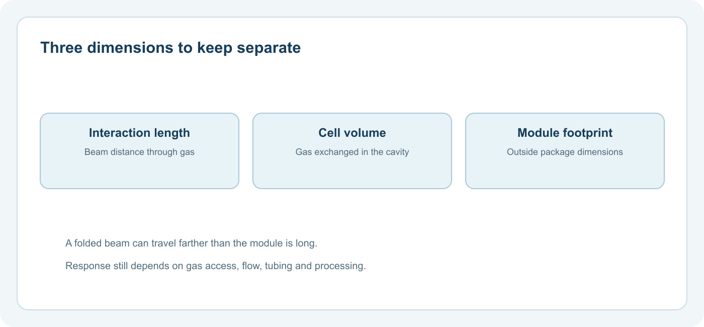
Interaction length is the effective distance traveled by useful infrared light through the gas. A beam that reflects through a cavity can have a longer interaction length than the cavity's straight physical dimension.
Gas-cell volume is the space exchanged with the surrounding or sampled gas. It affects gas exchange and potentially response time, but the relationship depends on openings, diffusion, pumping and flow. A small volume does not automatically mean a fast assembled device.
Module footprint is the outside size available to a designer. Electronics, seals, optical shielding and the source-detector arrangement all occupy space. A folded path can save footprint but may introduce alignment, contamination and light-loss considerations.
Sensirion describes how the SCD30's measurement cell is integrated into its PCB, allowing a thin transmissive NDIR module. That is a specific integration approach, not evidence that all small CO₂ sensors use the same length or optical layout. Vaisala's CARBOCAP explanation shows another important dimension of geometry: its absorption and reference wavelengths share one optical path, which helps its reference respond to common optical attenuation.
Geometry Also Affects Sampling and Maintenance
An optical cell is not only an equation. Gas must enter and leave it. A design with restricted openings can protect optics from dirt yet slow exchange with the environment. A pumped sample line can bring gas to the cell, but tubing, filters and condensate management become part of the response and maintenance burden. A sensor placed behind an enclosure vent can have a very different step response from a bare component tested in open air.
Contamination on a window or mirror may lower detected light. A reference architecture may reject some shared optical loss, depending on where the contamination occurs, but it cannot guarantee continued operation if the optical signal is too weak or the gas inlet is blocked. Read what an NDIR reference channel can compensate alongside path geometry rather than treating the two as independent features.
Temperature and pressure also matter because the density of gas molecules in the cell changes with conditions. A longer path does not make these influences disappear. The manufacturer's calibration, operating range and compensation inputs define the usable result.
How to Compare Two CO2 Sensor Designs
First, define the range where the reading will drive a decision. For a room monitor, that may be the normal occupied-air interval and its trends. For a greenhouse, the controlled band and excursions may differ. For a process sample, percentage-level operation and sample conditioning can dominate. The CO₂ ppm and percent guide helps express these ranges on the same fraction basis, but unit conversion alone does not establish sensor suitability.
Next, compare evidence from complete data sheets, not the optical diagram alone:
- Specified measurement and accuracy intervals. What error is guaranteed over the concentrations that matter?
- Operating conditions. What pressure, temperature, humidity and gas-composition limits apply?
- Response definition. Was response measured at the bare sensor, module or complete instrument, and under what airflow?
- Calibration and drift. Which reference conditions and service procedures are required?
- Integration. What are the real optical-cell openings, contamination protections, power and enclosure effects?
Các SCD30 datasheet is a useful example of why these fields must be separated. It distinguishes an interface range from an accuracy claim over a calibrated interval and provides test conditions. Those values describe that module only. The broader CO₂ measurement guide connects this component review to a finished instrument.
Do Not Infer a Detection Limit from Path Length Alone
“Longer path” sometimes appears as shorthand for “more sensitive.” A practical detection limit is influenced by light-source stability, detector and amplifier noise, optical throughput, background variation and how the instrument defines a detectable change. Resolution—the smallest displayed step—is another property entirely. Neither can be read from path length without the rest of the design and a stated test method.
Likewise, an extended digital output range does not mean the sensor has equal accuracy everywhere. The relevant figures are the manufacturer's specified range, error expression and conditions. When the claimed range is wider than the accuracy interval, decide which one covers the actual application.
For a complementary overview of optics, target-gas selection and calibration, see Gasnose's NDIR gas sensor guide. It helps explain why optical filter selection and path geometry must be designed together rather than selected as independent marketing specifications.
A Useful Design Rule
Choose the CO₂ concentration task first; then assess whether the complete optical and sampling system supplies enough contrast at the low end and enough received signal at the high end. Path length is one design variable inside that system, not a stand-alone measure of quality, miniaturization or accuracy.
Câu hỏi thường gặp
Does a longer path always improve CO₂ accuracy? No. It may increase low-concentration absorption, but added optical losses and reduced high-concentration transmission can work against a useful measurement. Accuracy also requires calibration and environmental control.
Is optical path length the same as sensor size? No. A beam can fold inside a compact enclosure, and the module's electronics and gas-cell volume are separate physical properties.
Can one NDIR module measure both outdoor background and high-percentage process CO₂ equally well? That depends on its specified accuracy range and calibration. Do not assume the output display or a path-length claim establishes that performance.
Does a small gas cell guarantee a fast response? No. Air access, flow, filters, tubing and firmware averaging can determine how quickly the complete device reports a change.