
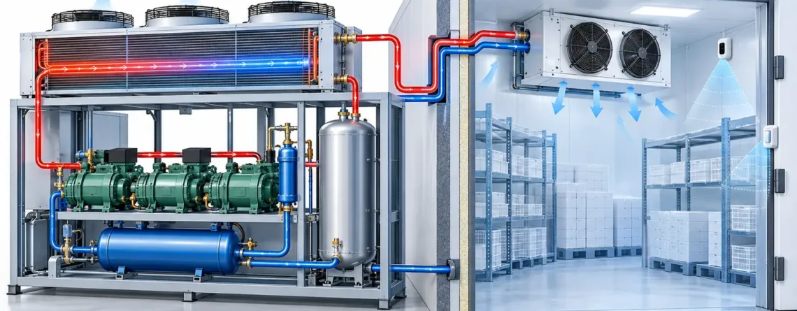
An R744 refrigeration system needs more than one kind of measurement. Pressure and temperature transducers observe carbon dioxide inside a closed, high-pressure refrigeration circuit so the controller can regulate and protect the plant. A fixed CO₂ detector samples air in a room where a release could affect people. A portable leak locator helps a trained technician find a source after a problem is suspected. These instruments see different places, answer different questions and cannot be substituted simply because all of them are associated with “CO₂.”
This separation is more useful than a generic description of R744 as a natural refrigerant. If a receiver pressure trend changes, the first explanation may be a control, load or ambient-temperature change rather than a leak. If a room detector alarms, it does not identify the failed joint or reveal whether the gas-cooler high-pressure control is correctly tuned. A monitoring plan should therefore name the physical sample, the decision to be made and the action owner for each channel.
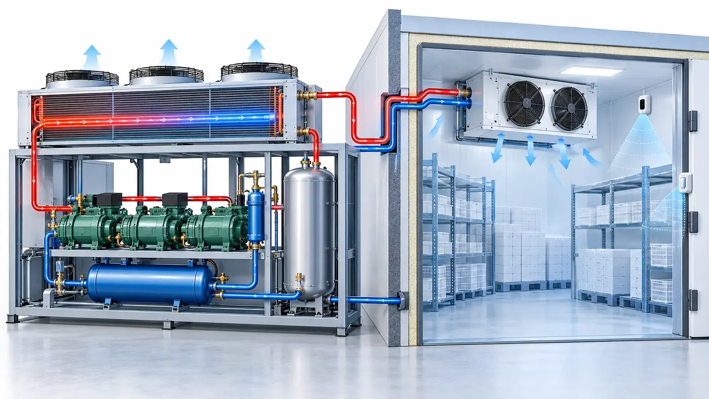
Three CO₂ questions, three measurement geometries
R744 is the refrigerant designation for carbon dioxide. In a plant drawing, “CO₂ sensor” may refer to an in-circuit pressure transducer, an air-sampling concentration detector, or a service leak instrument. The phrase is too imprecise for a specification. Use the table below to state what each device must actually observe.
| مهمة القياس | Physical sample and typical output | What it can support | ما لا يستطيع أن يثبته بمفرده |
|---|---|---|---|
| Process control and protection | Pressure/temperature in a defined refrigerant pipe, vessel or heat exchanger | Control of compression, receiver and expansion functions; trend and protection decisions within the equipment design | Concentration of CO₂ breathed in an occupied room |
| Occupied-space or plant-room monitoring | Air at one or more selected sampling locations; ambient CO₂ concentration or alarm state | Detection of an abnormal release in the monitored volume and initiation of the designed warning/ventilation sequence | Exact leak location or complete process diagnosis |
| Leak localization during service | Air close to a suspected joint or component as the probe is moved | Narrowing a suspected release to a serviceable location | Continuous room coverage while no technician is present |
An indirect alarm based on process data may also exist, but it remains a diagnostic inference. Process pressure, compressor cycling or receiver level can suggest an abnormal state without measuring the atmosphere in a cold room. Conversely, fixed ambient monitoring can establish that CO₂ is accumulating at a sample point without explaining why the refrigerant circuit behaved as it did. ASHRAE's Carbon Dioxide Refrigeration Systems chapter treats system pressure and occupied-space CO₂ monitoring as different design concerns; that distinction should carry through to the sensor schedule. Our guide to refrigerant sensor tasks compares these measurement jobs across refrigerants.
The refrigerant itself must also be identified correctly. A supplier's R744 entry in a refrigerant catalogue can help establish the designation and material context, but it cannot tell you where a particular plant needs pressure taps, room sampling points or safety controls. Those come from the engineered system and its applicable standards.
Why the refrigerant circuit needs several pressure and temperature points
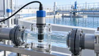
R744 has a much lower critical temperature and a different pressure envelope from many familiar HFC systems. Above its critical temperature, high-side heat rejection occurs in a gas cooler rather than as conventional condensation at a single saturation temperature. The controller therefore uses pressure and temperature together to interpret and regulate the high side. On the low and intermediate sides, the plant may include an evaporator, compressors, receiver, bypass arrangements or other architecture-specific elements. There is no useful “R744 system pressure” as one universal value.
ASHRAE's handbook chapter explains the subcritical and transcritical configurations and the need to understand operating and standstill pressure conditions. The Copeland commercial CO₂ handbook identifies pressure indications for low side, intermediate/interstage and high side, depending on architecture. A pressure sensor should be specified by the actual point and design envelope, not selected solely because it bears a refrigeration label.
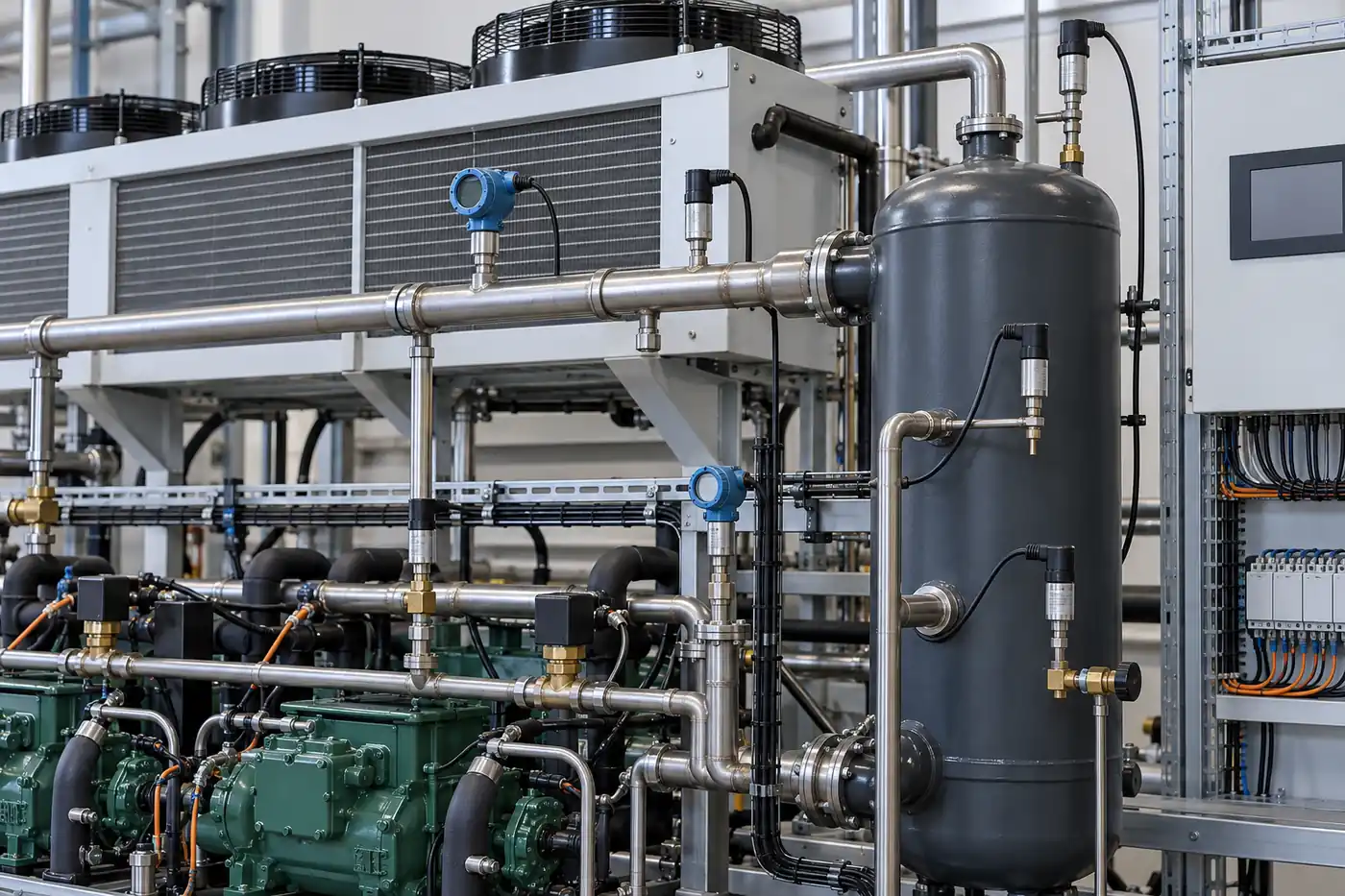
On a transcritical rack, gas-cooler outlet pressure and temperature contribute to high-side control and performance interpretation. Receiver or intermediate pressure supports the associated valve and bypass strategy. Suction pressure relates to evaporator and compressor operating conditions. Discharge temperature and pressure can inform compressor protection. These are examples of functions, not a universal instrument list: a cascade system, a compact integrated unit and a supermarket booster rack may place sensors differently.
For each point, read the machine maker's sensor specification and wiring diagram. Confirm the pressure range, maximum allowable pressure, overpressure tolerance, temperature limits, wetted material compatibility, connection type, electrical output and how a sensor failure is detected. A CO₂-compatible control valve or pressure transducer has a model-specific rating; Danfoss' transcritical CO₂ technical paper emphasizes that all components must be designed for adequate pressures. Do not transfer the rating of one component to an entire circuit.
Location also shapes what a number means. A high-side sensor downstream of the gas cooler does not measure exactly the same thermodynamic state as a discharge sensor at the compressor. A temperature sensor clamped poorly to an uninsulated pipe may lag or be biased by ambient air. A pressure transducer's accuracy statement does not compensate for a blocked port or wrong pressure reference. The drawing, physical installation and controller channel assignment should agree before a trend is interpreted.
Pressure trends are evidence, not a leak verdict
The intuitive thought “pressure is falling, so the system is leaking” can be wrong in an operating refrigeration plant. Compressor speed, expansion-valve position, gas-cooler airflow, load, ambient temperature, defrost, heat reclaim and receiver strategy can all change pressure. When the plant is off, standstill pressure can change with temperature even without a change in refrigerant mass. A single process value therefore cannot be converted into a leak rate by inspection.
A better interpretation asks four questions. أين is the sensor? In what state was the plant when the trend moved? What other channels moved at the same time? Is the deviation persistent after comparable operating conditions return? For example, a high-side pressure rise accompanied by warmer gas-cooler outlet temperature on a hot day may be consistent with changed heat rejection conditions. It is not proof of a release. A change in receiver level and repeated control instability under comparable loads may warrant investigation, but it still does not locate a leak.
The timing of logs matters. A controller archive that records pressure each minute but compressor mode only once per hour can make a normal transition look unexplained. Record valve commands, compressor state, defrost and alarm timestamps on the same clock where feasible. Keep engineering units and pressure reference explicit; gauge pressure and absolute pressure are not interchangeable in calculations. Sensor-quality issues—flatlined values, sudden implausible steps, communication faults—should be checked before attributing a process anomaly to refrigerant loss.
ال Copeland handbook is useful for understanding how multiple pressure zones and indications support service and control. It does not mean that an indirect trend substitutes for a fixed room detector where one is required by the safety design. The two channels answer different questions even when an advanced controller combines their alarms on one dashboard.
The room-air detector measures exposure at a location
Carbon dioxide in the refrigeration circuit is contained at pressure; a release into an enclosed area creates a different hazard. CO₂ is already present in normal outdoor and indoor air, but an equipment release can raise the concentration far beyond ordinary ventilation-indicator levels. It is nonflammable, yet a significant accumulation can impair breathing and create an oxygen-displacement hazard. The relevant question for a cold room or machinery space is whether people could encounter a dangerous concentration and how the designed alarm and ventilation response will operate. ASHRAE's R744 chapter addresses detection and ventilation when an occupied room could exceed the applicable refrigerant concentration limit.
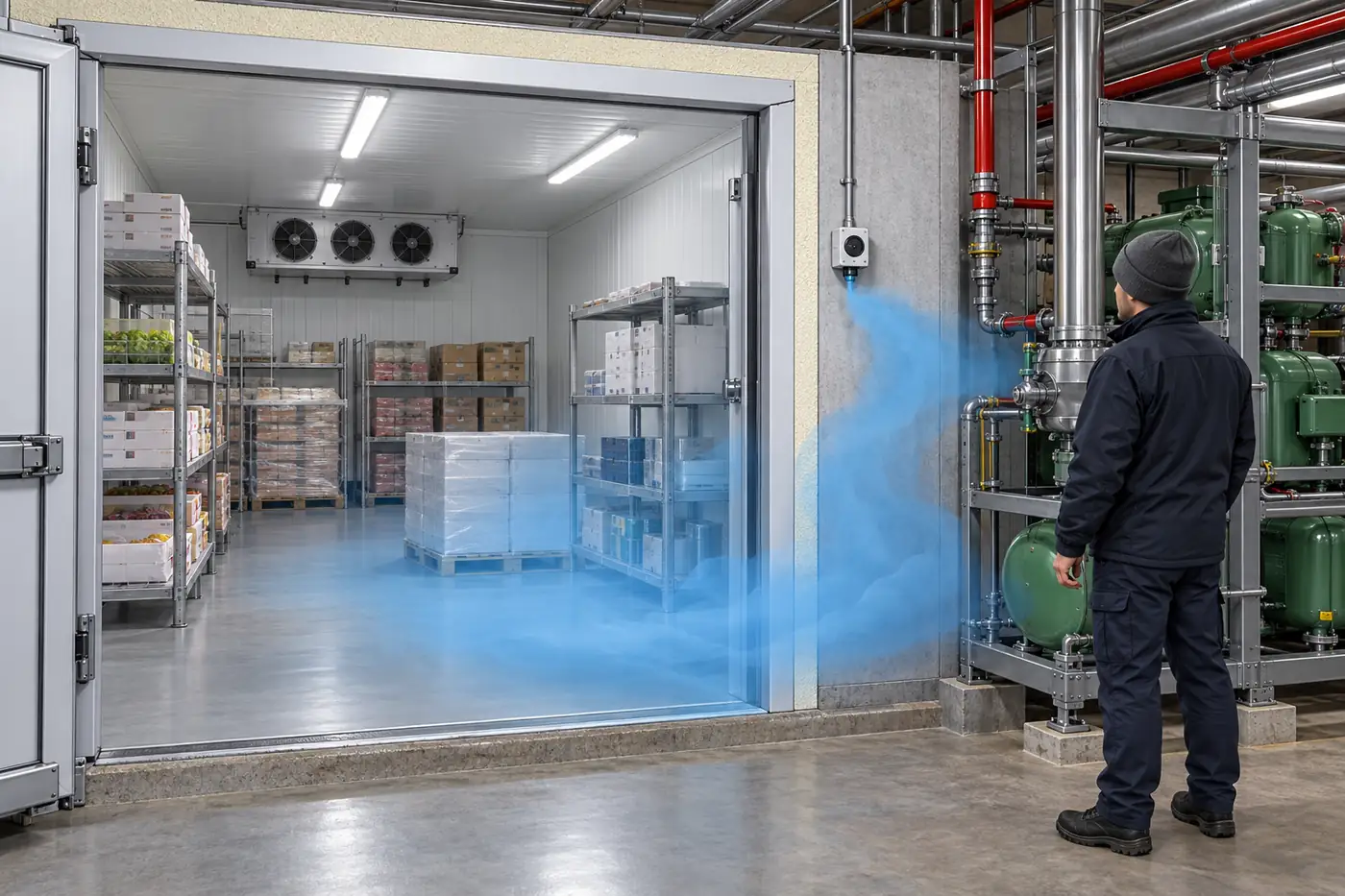
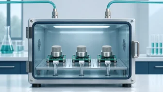
The colored plume in the illustration marks the area the detector is intended to observe; real carbon dioxide is invisible. A visible mist caused by rapid cooling is not a calibrated measure of CO₂ concentration. The image also cannot show whether the selected inlet will encounter a release under the room's actual airflow.
A fixed detector reports air at its inlet, not the mean concentration of an entire room. Sensor placement must account for the likely release points, room shape, machinery and doors, ventilation supply and exhaust, obstructions, air circulation, service access and the safety design. CO₂ density alone does not determine a universal mounting height. A discharge jet, warm or cold surfaces, fans and door traffic can change mixing. The designer should document why each point covers the intended scenario and whether more than one location or an aspirating arrangement is needed.
Select the room detector for the safety task, not for a convenient display
Start with the required detection purpose and the ambient concentration range that the project documentation actually calls for. Then check the detector's stated CO₂ range, accuracy or alarm tolerance near the intended decision point, response under the expected temperature and humidity, protection against condensation or wash-down, output type, fault indication and service interval. A warehouse cold room and a warm machinery space can expose detectors to very different environments. A specification that performs well in a dry laboratory at room temperature may not define behavior during a wet defrost cycle or when a cable connector is compromised.
The sampling method changes coverage. A fixed-point detector is located at the air it measures. An aspirating system draws air through tubing from one or more selected points; the tube length, flow supervision, sample sequence and possible delay become part of the performance chain. Neither architecture is inherently superior in every room. The design should state which places are sampled, what happens when a sample path is blocked, and how an alarm reaches people who may be inside a space with a closed door. A single display at the plant rack is not a substitute for a suitable warning at the location where people need it.
At handover, record the model and calibration gas, the installed sampling position, controller setpoints, notification devices, ventilation interface, fault behavior and the manufacturer's functional-check method. Check whether the alarm is visible to the building-management system and whether that system displays both alarm and detector fault as distinct states. A detector that reports normal because its communication failed is not a trustworthy safety channel. The scheduled verification procedure belongs to the installed equipment and applicable rules; do not invent a gas-release test from a general article.
Specify the detector for the expected monitoring range, environment and response purpose. An indoor-air-quality CO₂ display designed to indicate ventilation conditions cannot be assumed suitable as a refrigeration safety detector. Its range, response, fault handling, alarm logic, reliability assessment and control interface may be different. Likewise, a detector calibrated for another refrigerant should not be treated as an R744 detector because the mounting box looks similar. The intended gas, measurement range, environmental conditions and system role should all be explicit.
The alarm pathway needs its own review: what happens when concentration exceeds the design level, who is warned inside and outside the space, what ventilation or equipment action is commanded, and what happens if the sensor fails or loses power? The required setpoints and response sequence depend on the current applicable standard, jurisdiction and equipment assessment. An article cannot set those values for an unknown room. The Institute of Refrigeration's R744 safety code offers a professional framework for reading the relevant UK/European design requirements; local projects must use their own adopted rules and current editions.
An ambient alarm is also not a service clearance. After an abnormal event, qualified personnel follow the site's emergency and re-entry procedures and use suitable instruments. A monitor at one point returning to a normal reading does not prove that every pocket of a room is clear or that the leak has been repaired. Its measured location and alarm record are valuable evidence within a broader response plan.
Portable localization answers the next question
Once a fixed detector, process anomaly or routine inspection suggests a release, a technician may need to find its source. A portable instrument is moved close to candidate joints, valves, seals and other accessible parts. Its job is spatial localization. It may respond differently when held near a plume than a fixed monitor does several meters away, and it should be chosen for R744 and the specific service conditions.
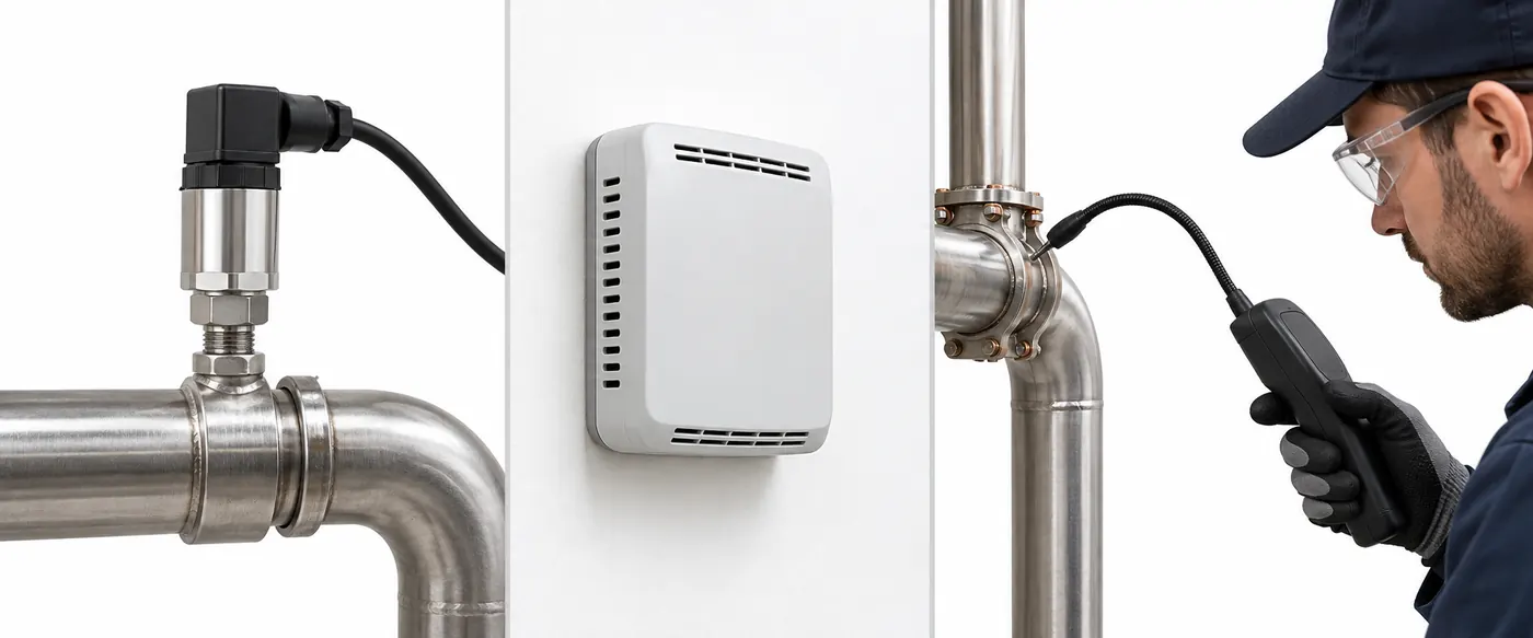
This is why a portable detector is not a permanent substitute for a fixed monitor in a space that requires continuous protection. No one is sampling the room after the service visit ends. Equally, a fixed alarm does not identify which connection failed. Even a process controller that notices an abnormal charge-related trend will usually need a separate method to locate a physical leak. The three instruments form a sequence of detection, context and localization when the engineered design calls for them.
A service procedure should distinguish a gas detector's indication from other evidence such as oil residue, pressure history or a manufacturer-approved leak test. Electronic instruments have their own selectivity, response, recovery, maintenance and calibration requirements. The qualified technician follows the specific equipment instructions and site procedures, especially because R744's pressure and low-temperature effects make intrusive service hazardous. This article describes the roles of instruments; it is not a step-by-step method for opening or testing a pressurized circuit.
The question after localization is also different from the question before it. A portable signal near a valve can prioritize inspection, but it does not by itself quantify the released mass or establish that the repaired circuit will remain tight. The service record should identify the instrument, its checks, the suspected location, the method used to verify the repair and the subsequent monitoring observations. If a fixed detector later alarms again, that history narrows the next investigation without turning the first probe indication into an exact leak-rate measurement.
Instrument specifications may use different units: an ambient detector might report ppm or percent by volume, while a handheld locator may advertise a minimum detectable leak rate under a defined test method. Those figures are not directly comparable. The leak-rate claim concerns a controlled local release and probe technique; the fixed detector's concentration depends on room volume, ventilation, release duration and sample location. Select each instrument against its own job rather than ranking two unlike numbers on a sales sheet.
Read the channels together without mixing their meanings
The most useful dashboard puts unlike signals next to each other while preserving their units and sample locations. A high-side pressure curve, gas-cooler outlet temperature, receiver pressure and compressor state can explain a process transition. A separate room CO₂ channel can indicate whether that space is affected. A service log can record where a technician subsequently localized a release. None should be silently relabeled as “CO₂ leak level.”
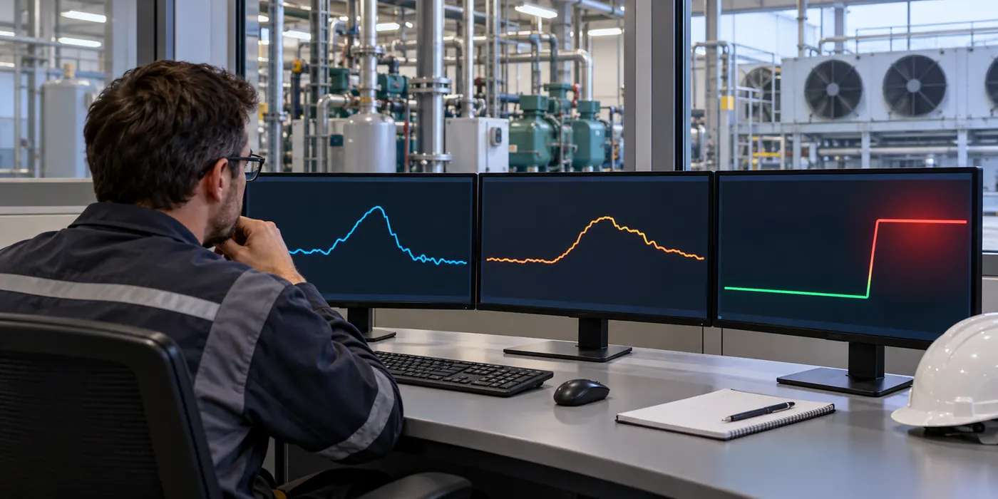
Consider a conditional example. During a warm afternoon, high-side pressure rises while gas-cooler outlet temperature also rises; room CO₂ stays near its ordinary baseline and no ambient alarm occurs. The observations may fit changing heat-rejection conditions, but the correct interpretation depends on the actual control strategy and operating state. They do not establish the absence of a small leak. If, in a different scenario, a room detector indicates a sharp CO₂ increase near a plant enclosure while process channels do not yet show a clear change, the room event still requires the designed response. A short release into a small volume may be visible to ambient monitoring before inventory changes become obvious in plant trends. These examples illustrate reasoning, not measured case histories.
A second conditional example involves an apparent process anomaly with no ambient alarm. The anomaly could reflect control, load, sensor fault or a release outside the monitored space. The lack of a room alarm does not rule out every leak path; it says only that the detector did not report the specified alarm condition at its sample point in that interval. Review sensor health, coverage and operating context, then investigate according to the plant procedure.
For a design review, build a measurement register rather than a vague list of “CO₂ sensors”:
| Point | Sample location | Units and normal context | Decision/action | الأدلة اللازمة |
|---|---|---|---|---|
| High-side pressure | Named pipe point | Pressure reference, range, compressor/gas-cooler state | التحكم/الحماية | OEM schematic and transducer rating |
| Gas-cooler outlet temperature | Named pipe or probe well | Temperature, ambient/load condition | High-side interpretation | Sensor placement and controller logic |
| Receiver/intermediate pressure | Named vessel/line | Pressure and operating mode | Valve/receiver strategy | Architecture drawing and setpoint basis |
| Room CO₂ | Exact air sampling point | Ambient concentration or alarm state | Warning/ventilation response | Coverage study, detector manual and applicable standard |
| Portable leak indication | Service probe near candidate location | Instrument indication under service procedure | Localize for repair | R744 instrument specification and service record |
This register also helps a reader of a product catalog. A pressure transducer and an ambient gas detector may both be sold as “CO₂ sensors,” but their process connections, measuring ranges, environments and outputs have little in common. The selection should start with the row's measurement job.
Common specification mistakes
Using an IAQ CO₂ meter as a room safety detector. An ordinary ventilation monitor may be useful for comfort or air-exchange observations, but its range and alarm system may not meet the refrigeration safety task. Read the actual detector and system documentation.
Treating stable pressure as proof of a safe room. Pressure is influenced by operating state and temperature, and a localized room release can matter before a broad plant trend is decisive. Measure room air separately where the safety design calls for it.
Treating a room alarm as a leak map. The detector identifies a concentration at a point. Air movement, multiple leak sources and delayed transport make exact localization a separate service task.
Reusing components from a lower-pressure refrigerant design. A familiar connection size or output signal does not prove that the wetted component, fitting or assembly is rated for the R744 pressure and temperature envelope. Confirm every component against the machine design and its maximum allowable conditions.
Copying a universal alarm setpoint from a blog. Alarm levels depend on the applicable code, room use, detector location, risk assessment and response design. Verify the current governing documents for the specific project. A number without those conditions is not a safe specification.
Ignoring sensor faults and timestamps. A flatline can be a measurement failure, and unsynchronized logs can make normal transitions look causally linked. Include fault states, calibration and clock quality in the monitoring design.
أسئلة كثيرا ما يطرحها القراء
Is R744 CO₂ the same gas measured by an indoor-air-quality CO₂ monitor?
Chemically it is carbon dioxide, but the instruments may be designed for very different concentration ranges, response requirements and system actions. The intended use of a detector cannot be inferred from the gas name alone. Use a device and complete alarm system specified for the safety task where required.
Can a high-pressure sensor detect a refrigerant leak?
It can contribute indirect evidence of abnormal circuit behavior, especially when combined with operating state and other points. It does not measure room concentration or locate a joint. A pressure change may have other causes, and a small or localized release may not be obvious in a single trend.
Why measure both high-side pressure and gas-cooler outlet temperature?
In transcritical operation, interpreting and controlling heat rejection requires both pressure and temperature context. A pressure number without the corresponding thermal and control state can be misleading. The exact control method and sensor locations belong to the specific equipment design.
Where should a fixed R744 detector go?
The engineering answer depends on the space, release scenarios and air movement. The designer follows the applicable safety requirements and equipment documentation and checks that the selected point samples the intended hazard. There is no one mounting height that can be prescribed for every cold room or machinery space.
Is a portable leak detector enough if the plant has a controller alarm?
It helps localize a source during attended service. It cannot provide unattended room coverage. Whether fixed monitoring is required and how its outputs must act is determined by the installed-system safety design and local rules.
R744 monitoring works when each measurement has an honest name. Circuit sensors tell the controller about refrigerant process conditions; room detectors report air at their sampling points; service instruments help find a physical release. Combining those records supports better diagnosis, but combining their labels obscures what each instrument actually knows.






اترك رد