
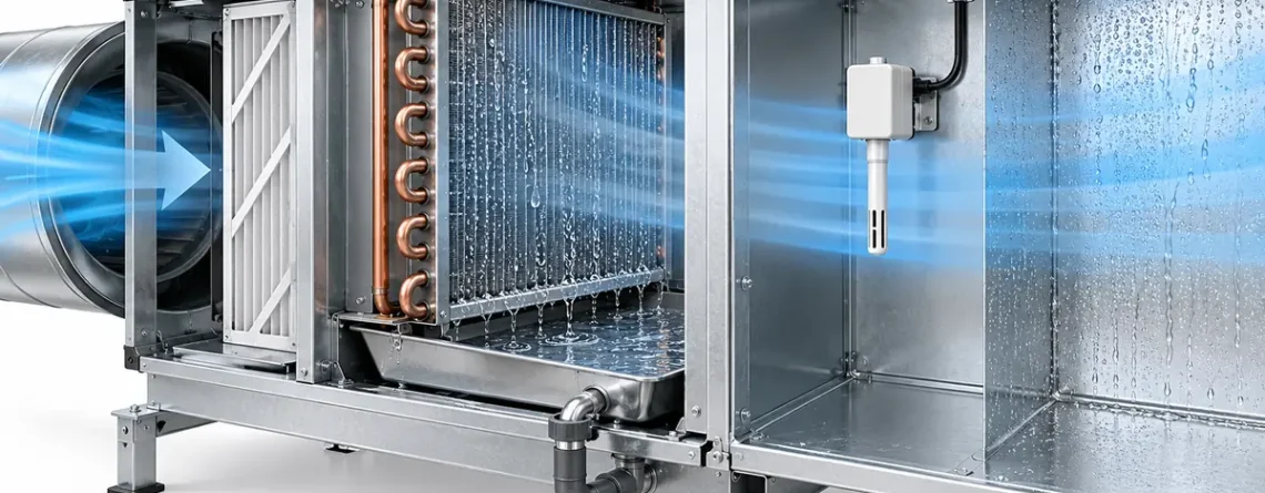
Kondensation wird zu einem Messproblem, wenn flüssiges Wasser ein Sensorelement, einen Einlass, einen Filter, eine Leiterplatte oder einen Kabeleingang erreicht, der eher für die Messung von Luft als von Wasser gedacht war. Die sinnvolle erste Frage lautet nicht „Wie hoch ist die Luftfeuchtigkeit im Raum?“ Aber Welche Oberfläche wurde kälter als der Taupunkt der sie umgebenden Luft? Eine Kühlschlange soll bei der Entfeuchtung Wasser sammeln und ableiten. Eine Kanalfeuchtigkeitssonde, ein Gasdetektor oder ein Steuermodul daneben dürfen nicht dafür ausgelegt sein, nass zu werden. Diese beiden Formen von Feuchtigkeit müssen unterschieden werden, bevor ein Messwert, ein Alarm oder eine Störung interpretiert wird.
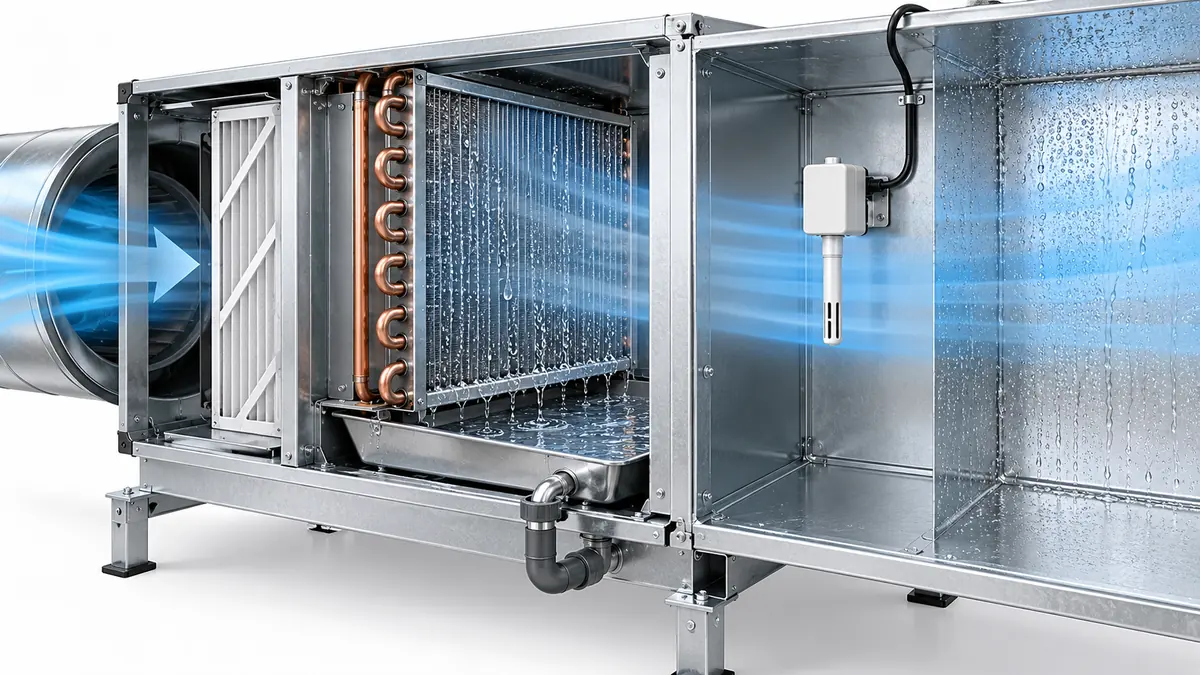
This guide is for people choosing, installing or troubleshooting HVAC sensors around cooling coils, outside-air sections, humidifiers, chilled beams and equipment cabinets. It explains how to separate air conditions from surface conditions and how to read a sensor's environmental specification. It does not make a generic sensor waterproof or set an installation position for every air handler. The final position and response to a wet safety device come from the actual instrument and equipment instructions.
Drei verschiedene Orte können „nass“ sein
Absichtliche Kondensation im Register. A cooling coil removes moisture because its cold surface contacts air whose dew point is higher than the coil surface temperature. Liquid water should collect on the coil and flow to a drain pan. In that part of the process, water is expected; a clogged drain or carryover into the downstream airstream is not. A sensor installed after the coil may encounter saturated air, droplets or splashing even if a sensor upstream sees ordinary relative humidity.
Unwanted wetting at the measurement point. A duct probe or gas-sensor inlet may see mist, a local cold surface or water trickling along the probe body. An RH element measures water vapor under its specified conditions; a water film on its protective cap is a different boundary condition. A temperature probe immersed in a drop can approach the water temperature rather than the intended air temperature. A gas inlet blocked by water can delay or prevent the target gas from reaching the sensing chamber.
Condensation on the electronics or cable path. Die Luft innerhalb eines Gehäuses, der Kanal außerhalb und der Kabelkanal können unterschiedliche Temperaturen haben. Eine kalte Metallwand oder Wärmebrücke kann Wasser sammeln, selbst wenn die Sondenspitze trocken bleibt. Wasser kann dann durch eine nicht abgedichtete Armatur in Richtung einer Leiterplatte fließen. Eine Einstufung des Gehäuses, falls vorhanden, allein beweist nicht, dass ein Gaseinlass oder ein RH-Element im nassen Zustand funktionieren kann.
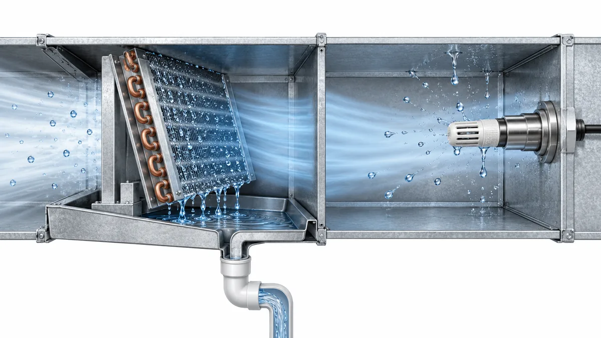
These cases lead to different fixes. Moving a humidity probe cannot repair a failed drain pan. Replacing a sensor cannot remove a persistent thermal bridge. Improving enclosure sealing cannot make a measurement representative if the probe is still in a spray plume. Identify the wet surface and the water path before choosing a remedy.
Dew point belongs to the local air, while condensation belongs to a surface
Relative humidity tells how close a parcel of air is to saturation at its present temperature. Dew point expresses the temperature at which that air would reach saturation if cooled without changing its water content. Condensation begins at a surface when the surface is sufficiently cold relative to the dew point of the air touching it. The surface may be the coil, a pipe, a probe stem, a duct wall or an electronics enclosure. The relevant temperature is surface temperature, not just the display value from a wall thermostat.
For example, an air handler may draw humid outdoor air past a cold duct penetration. The average return-air RH can be moderate while the metal around the penetration is below the local dew point. Conversely, air immediately leaving a wet cooling coil can be close to saturation while a warm transmitter head outside the insulated duct stays dry. Neither observation contradicts the other. It describes two different air-and-surface pairs.
Honeywell's humidity sensor theory guide erklärt, dass die Kondensation von der aktiven Sensoroberfläche im Verhältnis zum Taupunkt des umgebenden Gases abhängt und dass Wasser aus einem benetzten Element langsam verdunsten kann. Eine RH-Spur, die nach einem Abkühlungs- oder Befeuchtungsereignis schnell ansteigt und sich langsam erholt, kann daher auf lokale Benetzung zurückzuführen sein. Es könnte sich auch um eine tatsächliche Änderung der Luftfeuchtigkeit, einen verschmutzten Filter oder eine Glättung des Reglers handeln. Die Form allein ist keine Diagnose.
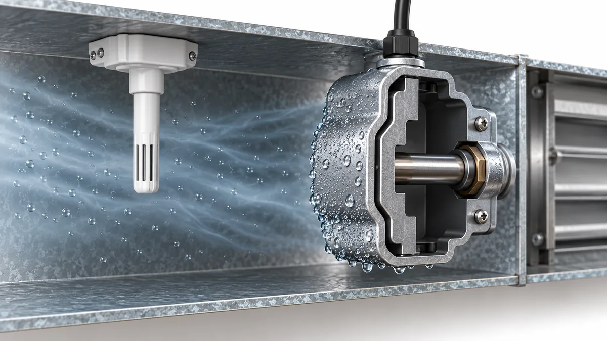
The most useful comparison records air temperature and RH at the intended sampling point, an independent estimate of local dew point, and the temperature of the suspected cold surface. If the air is stratified or the surface is intermittently cooled, one average value will hide the critical period. Log the fan, coil, humidifier and defrost states at the same time. Avoid presenting a calculated dew point as a directly measured surface temperature.
Choose a location for the variable you actually need
Ein HVAC-System enthält mehrere gültige, aber unterschiedliche Luftproben. Die Außenluft bezeichnet die wetterseitige Belastung. Rückluft spiegelt eine Mischung aus Aufenthaltsräumen wider. Luft unmittelbar hinter einer Kühlschlange beschreibt einen kalten und möglicherweise nassen Prozesszustand. Weiter stromabwärts kann die Zuluft wärmer, besser gemischt und besser für einen Regelsensor geeignet sein. Eine Rohroberfläche oder ein Kühlpaneel hat noch eine weitere Aufgabe: Sie warnt vor Kondensation auf dieser Oberfläche.
| Beabsichtigte Entscheidung | Nützlicher Messpunkt | Feuchtigkeitsproblem, das überprüft werden muss | Häufige Fehlinterpretation |
|---|---|---|---|
| Kontrollieren Sie den Komfort oder die Belüftung des Raums | Repräsentativer Rückflug oder Luftverkehr in besetzten Zonen | Wandeffekte, Schichtung, lokale Wärme- und Feuchtigkeitsquellen | Treating one return-duct RH as every room's RH |
| Messen Sie die Entfeuchtung der Spule | Vor und nach der Spule mit geeigneter Temperatur-/Feuchtigkeitsinstrumentierung | Gesättigte Abluft, mitgerissene Tröpfchen, Abflussverschleppung | Vorausgesetzt, jede nachgeschaltete RH-Sonde kann Tröpfchen tolerieren |
| Steuern Sie einen Kanalbefeuchter | Standort mit ausreichend gemischtem Wasserdampf | Nebel oder nicht absorbierter Dampf erreichen eine Sonde | Behandeln eines lokalen Grenzwertsignals als durchschnittliche Kanalfeuchtigkeit |
| Vermeiden Sie Kondensation an gekühlten Oberflächen | Oberflächensensor oder Lufttaupunktschätzung gepaart mit der Oberflächentemperatur | Wärmekontakt, wechselnde Raumluft, Kabelwärmebrücken | Vergleich der Raum-RH allein mit der Rohrtemperatur |
| Erkennen Sie Kältemittel oder andere Gase in der Nähe von HVAC-Geräten | Vom Hersteller genehmigte Position und Einlass des Gasdetektors | Wasser oder Schmutz am Einlass, Luftstromveränderungen, Gehäusekondensation | Ein unplausibles Gassignal als Leck oder Fehlalarm bezeichnen, ohne den Einlass zu überprüfen |
Der Munters Entfeuchtungshandbuch unterscheidet die sehr feuchte Luft unmittelbar nach einer Kondensationsschlange von anderen HVAC-Probenahmepunkten. Eine Sonde, die für normale Mischluft ausgewählt wurde, sollte nicht in einen mit Tröpfchen beladenen Rohrschlangenauslass verlegt werden, nur weil dieser Ort praktisch ist. Ebenso benötigt ein nach einem Luftbefeuchter platzierter Sensor einen ausreichenden Mischabstand für das tatsächliche Gerät und die Kanalgeometrie. Johnson Controls' HE-69xx0NP installation guide gibt eine modellspezifische Standort- und Kondensatwarnung; seine Abmessungen und Abstände sind keine allgemeingültige Regel für alle Sonden.
Before accepting a location, ask what the controller will do with the value. If an RH sensor controls dehumidification, does it represent the room, the return mixture or the cold coil discharge? If a temperature probe controls a freeze-protection sequence, is it on the intended section of coil or in a warm bypass stream? If a gas detector is safety-related, use its equipment's approved position and service instructions rather than applying humidity-sensor placement advice to it.
What wetting can do to different sensor types
Das Ergebnis hängt vom Sensorprinzip, der Verpackung und der Belichtung ab. Es ist technisch nicht sinnvoll zu sagen, dass „Feuchtigkeitssensoren im Wasser versagen“ oder dass „optische Sensoren die Feuchtigkeit ignorieren“. Wasserdampf, Flüssigkeitstropfen und Wasser auf einer optischen Oberfläche stellen besondere Herausforderungen dar.
Kapazitive RH-Elemente commonly respond to water vapor through a moisture-sensitive film. If the protective cap or active region becomes wet, the displayed value may remain near saturation and recovery may lag after the air dries. The element may recover when the film dries, but contamination deposited during wetting can affect later behavior. Honeywell's theory guide describes the importance of wetting and drying dynamics; the decision to reuse a particular assembly belongs to its manufacturer instructions and a subsequent check.
Lufttemperatursonden können eine lokale Temperatur genau messen, aber die Frage falsch beantworten, wenn ein Tropfen, eine kalte Montagehalterung oder eine strahlungskalte Wand ihren thermischen Kontakt dominiert. Ein Sensor kann elektrisch einwandfrei sein, obwohl er durch die Installation vorgespannt ist. Der Unterschied zwischen Lufttemperatur und Oberflächentemperatur ist besonders wichtig für die Taupunktkontrolle. Ein Oberflächenthermistor muss an der Oberfläche angebracht werden, der er folgen soll. Eine Luftsonde sollte nicht als Rohrsensor behandelt werden, da sie in der Nähe sitzt.
Gasdetektoren have inlets, diffusion barriers, filters and sometimes optical paths. Liquid water can obstruct diffusion or change a sample path. A wet module can also create electrical faults or unreliable readings. The response varies by design; do not assign a universal direction of error. If a safety-related detector becomes wet or signals a fault, follow the equipment's prescribed fault procedure rather than declaring the atmosphere safe from one displayed number. For broader humidity mechanisms, see our Anleitung zur Luftfeuchtigkeit von Gassensoren.
Optische und Partikelgeräte may be affected by droplets, fog or condensation on optical surfaces, but their interpretation depends on the instrument and measurement target. A PM sensor may count hygroscopic growth or droplets as particles, while an NDIR gas module may face moisture effects through an optical path or inlet. Those are not interchangeable mechanisms. An instrument's humidity compensation may address a characterized vapor effect without making liquid-water exposure acceptable.
Lesen Sie jedes Datenblatt für den Betrieb mit relativer Luftfeuchtigkeit, ob Kondensation ausgeschlossen ist, den Einlassschutz, Anweisungen zur Rückgewinnung und den spezifischen Temperaturbereich, für den die Leistung angegeben ist. Zum Beispiel die Winsen ZRT512E refrigerant module page listet seinen eigenen Arbeits-RH-Bereich mit a auf „Keine Kondensation“ Qualifikation. Dieser Wortlaut ist für eine Nassschrank-Entscheidung wichtiger als ein beeindruckender oberer RH-Wert allein. Es stellt nicht sicher, dass ein anderes Modell denselben Grenzwert hat.
Durch Wärmebrücken und Montagegeometrie kann eine lokale Nassstelle entstehen
A duct probe crosses a boundary between duct air and ambient plant-room or attic air. Its metal stem, mounting plate, fasteners and cable can conduct heat across that boundary. A cold stem may be below the surrounding air's dew point even if the main duct is insulated. A warm transmitter head can also heat the probe or temperature element. Vaisala's duct-installation guidance Der Schwerpunkt liegt auf der Montage des Kopfes innerhalb der Isolierhülle und der Verhinderung einer Wärmeübertragung, die zu Kondensation und falschen Messwerten führt.
Orientation determines where any water can flow. A downward-pointing probe may lead droplets toward the sensing element or cable entry in some designs; another probe may explicitly prohibit a different orientation. Follow the manufacturer's permitted positions and mounting drawing. Do not turn one supplier's orientation advice into a rule for every sensor. A mounting flange can also channel wash water or condensate around a gasket. Inspect the assembled cable gland and conduit path, not only the sensing tip.
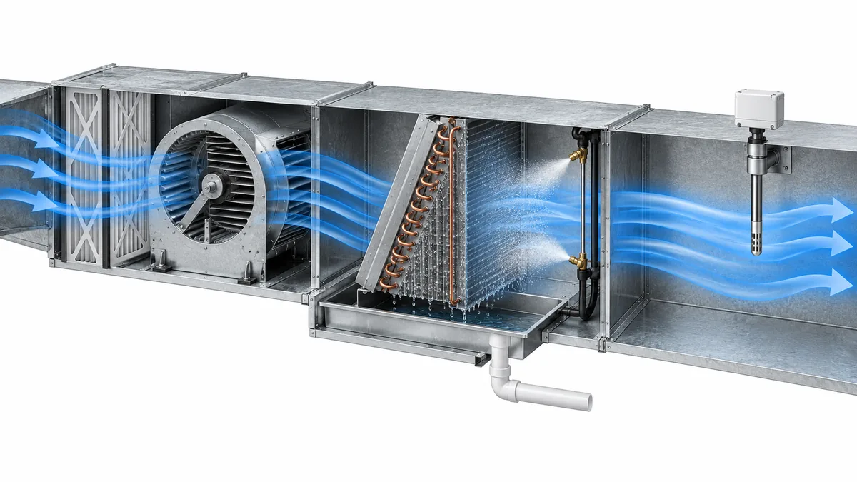
Der Luftstrom ändert sich je nach Betriebsmodus. Ein Sensor, der bei eingeschaltetem Lüfter trocken bleibt, kann nach dem Abschalten kalte, stehende Luft erkennen. Abtauung, Betrieb des Außenluft-Economizers, Befeuchtungswechsel und Kühlung bei geringer Last können die Beziehung zwischen Taupunkt und Oberflächentemperatur verändern. Die Standortüberprüfung sollte die Modi umfassen, die das Gerät tatsächlich nutzt. Ein einziger Schnappschuss bei konstantem Volllastbetrieb reicht nicht aus, um nachzuweisen, dass die Sonde niemals nass wird.
Eine praktische Diagnose beginnt mit einem Zeitplan, nicht mit einem Ersatzteil
When a reading becomes implausible after cooling or humidification starts, preserve the controller trend before resetting or replacing anything. Record the sensor's raw value if available, engineering units, timestamp, fan state, coil valve or compressor state, humidifier command, outdoor and return-air conditions, and any device fault flag. If the controller filters or averages the signal, note the update period. A delayed display can come from software as well as from a wet cap.
Then compare three observations: the intended air sample, the suspect sensor's physical condition, and a suitable independent reference. A handheld meter placed elsewhere in the duct does not automatically invalidate the fixed sensor; it may be sampling a different air stream. Put the reference where it reasonably samples the same mixed air, using the reference instrument's own settling time and humidity limits. If the suspect probe is near a drain leak or humidifier plume, photograph the water path and record the operating mode rather than relying on one RH reading.
The following sequence separates the most common explanations without requiring a made-up test gas or unsafe bypass:
- Identify the measurement task. Confirm the intended location and model from the equipment drawing and sensor manual.
- Inspect water routes. Look at coil carryover, drain pan, spray source, cold stem, insulation gap, cable entry and enclosure. Do not open energized safety equipment contrary to its service instructions.
- Compare local conditions. Record air temperature/RH and likely cold-surface temperature, with uncertainty and sensor placement documented.
- Check the signal path. Distinguish a true sensor output from an analog scaling error, stale digital value, wiring fault or controller substitution.
- Observe recovery or prescribed service. Follow the manufacturer-approved drying, inspection, replacement and functional-check instructions. A return to a plausible number alone is not proof of qualified performance.
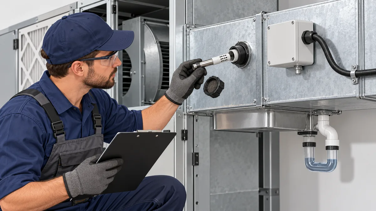
If the same event recurs, redesign the measurement location or water-management path rather than repeatedly replacing a sensor. A new device in the same wet location can show the same symptom. If the sensor participates in an alarm or protection function, maintain the required safe state while its condition is investigated; a building-automation trend is not authorization to defeat that function.
Read environmental specifications as separate promises
An instrument data sheet may contain an operating temperature range, an RH range, an ingress rating, an accuracy statement, a response-time test and a storage limit. Each can be true under different conditions. A device that survives storage in a damp package is not necessarily specified to measure accurately while condensed water covers its inlet. An enclosure IP rating may protect electronics but leave the exposed sensing tip subject to a stricter condition.
For a specification review, write down the exact model and revision, then answer these questions:
| Frage | Evidence to locate | Why it changes the decision |
|---|---|---|
| Is liquid condensation allowed during measurement? | Explicit noncondensing/condensing language, not just maximum RH | Water vapor limits cannot be used as droplet tolerance |
| Which part is rated? | Element, probe, transmitter head, cable and inlet drawing | An enclosure rating may not cover the exposed sensor |
| What are the accuracy test conditions? | Temperature, RH, airflow, pressure and stabilization | A room-temperature accuracy number may not apply after cold start |
| What happens after wetting? | Recovery, cleaning, recheck or replacement instruction | Plausible output after drying may still need verification |
| How is failure signaled? | Fault bit, analog out-of-range behavior or relay state | The controller must not interpret a fault as clean air |
| How is it installed? | Approved orientation, insertion length, insulation and service access | Geometry determines both sample and water path |
A useful purchasing requirement is not “waterproof sensor.” It is a defined task and environment: what air or surface is measured, likely spray and condensation exposure, required accuracy and response, permitted mounting, and the action on failure. A supplier can then provide a model-specific data sheet and installation guide. Where a location is unavoidably wet, a sensor intended for that environment and measurement task may be necessary; a generic duct RH probe should not be assumed adequate.
Compare the symptom with the water path
An efficient site visit begins with a sketch of the air handler and its thermal boundaries. Mark the outside-air intake, mixing section, filter, coil, drain pan, humidifier, supply duct and each sensor. Then mark which surfaces are insulated and which penetrations connect warm and cold spaces. This simple drawing can reveal that a transmitter head is in a warm plant room while its metal probe stem crosses a cold duct wall, or that a cable conduit is carrying humid air toward a colder enclosure. Those details may be invisible in a building-management trend.
Next compare independent observations, not just two numbers from the same controller. A room RH sensor may show a normal average while a duct probe is repeatedly wetted by local droplets. A handheld humidity instrument used briefly at the same point can help distinguish a local air condition from a failed permanent element, but only if the instruments are allowed to equilibrate and their own temperature and accuracy limits are respected. A contact measurement of the suspicious surface and an estimate of the nearby air's dew point can clarify whether condensation was physically plausible. Neither reading should be represented as a laboratory validation unless it was taken and documented under an appropriate method.
The symptom's timing can narrow the search. If an RH signal sticks near saturation only during cooling and slowly recovers after the coil is off, inspect the downstream wet-air path, drain and sensor cap. If the instrument faults after the enclosure is cold-soaked and then returns as the room warms, inspect the electronics housing, cable entry and thermal bridges. If multiple sensors change at the same moment, check a real process event or shared control/power problem before replacing all of them. These are investigation cues, not proof of a specific failure mode.
Dokumentieren Sie, was tatsächlich gefunden wurde: Tröpfchen auf einer Sonde, eine nasse Kabelverschraubung, ein verstopfter Abfluss, ein intakter, aber schlecht platzierter Sensor oder keine sichtbare Feuchtigkeit. Notieren Sie den Betriebsmodus, die Luft- und Oberflächenbedingungen, den Sensorstatus, Fotos und die entsprechende Revision des Handbuchs. Ein reparierter Abfluss verhindert möglicherweise eine erneute Verschleppung, kann jedoch ein kontaminiertes RH-Element nicht automatisch wiederherstellen. Umgekehrt kann es sein, dass ein neuer Sender auf der Werkbank funktioniert und den gleichen Fehler wiederholt, wenn er an der ursprünglichen Kaltdurchdringung installiert wird. Die Endkontrolle sollte sowohl den Wasserweg als auch die Messaufgabe unter repräsentativen Betriebsmodi bestätigen.
FAQ
Kann ein Kanal-RH-Sensor 100 % anzeigen, auch wenn der Raum nicht so feucht ist?
Ja. Der Kanalstandort kann kälter, gesättigter oder feuchter sein, während die Luft im Aufenthaltsbereich anders ist. Der Sensor kann auch Wasser auf seiner Kappe zurückhalten und sich langsam erholen. Vergleichen Sie eine geeignete Referenz am gleichen Probenahmeort und überprüfen Sie den physikalischen Zustand, bevor Sie entscheiden, ob der Raum oder der Sensor falsch ist.
Ist Kondensation hinter einer Kühlschlange immer ein Defekt?
Wasser auf der Spule und in ihrem Abflusssystem ist ein erwarteter Teil der Entfeuchtung. Tröpfchen, die in eine Messsonde gelangen, Lecks aus der Wanne oder Feuchtigkeit, die in die Elektronik gelangt, sind unterschiedliche Bedingungen. Dokumentieren Sie, wo sich das Wasser befindet und ob es dem vorgesehenen Abflussweg folgt.
Verhindert die Temperaturkompensation Kondensationsfehler?
No. Compensation can correct a characterized temperature dependence of a sensor under specified conditions. It does not remove a water film, open a blocked gas inlet or seal a cable gland. Check the actual module's environmental qualifications.
Kann ich anhand einer RH-Messung entscheiden, ob eine Pfeife schwitzt?
Nur mit der entsprechenden Lufttemperatur, einer vertretbaren Taupunktberechnung und der Rohroberflächentemperatur am Störort. Die Oberfläche kann kälter sein als die Luft; Ein Raum-RH-Wert allein reicht nicht aus. Befolgen Sie das Design der Kühlflächensteuerung für die installierte Ausrüstung.
Wann kann ein benetzter Sensor wieder in Betrieb genommen werden?
Das hängt von der Konstruktion, der Belichtung und den Herstelleranweisungen ab. Protokollieren Sie das Ereignis und alle erforderlichen Trocknungs-, Inspektions-, Austausch- oder Funktionsprüfungen. Bei einem sicherheitsrelevanten Melder bedeutet eine scheinbar normale Anzeige nach der Befeuchtung nicht automatisch eine erneute Eignung des Geräts.








Kommentar (1)
[…] the HVAC case, see our separate discussion of condensation around HVAC sensors. This article concentrates on specifying the dew-point measurement […]