
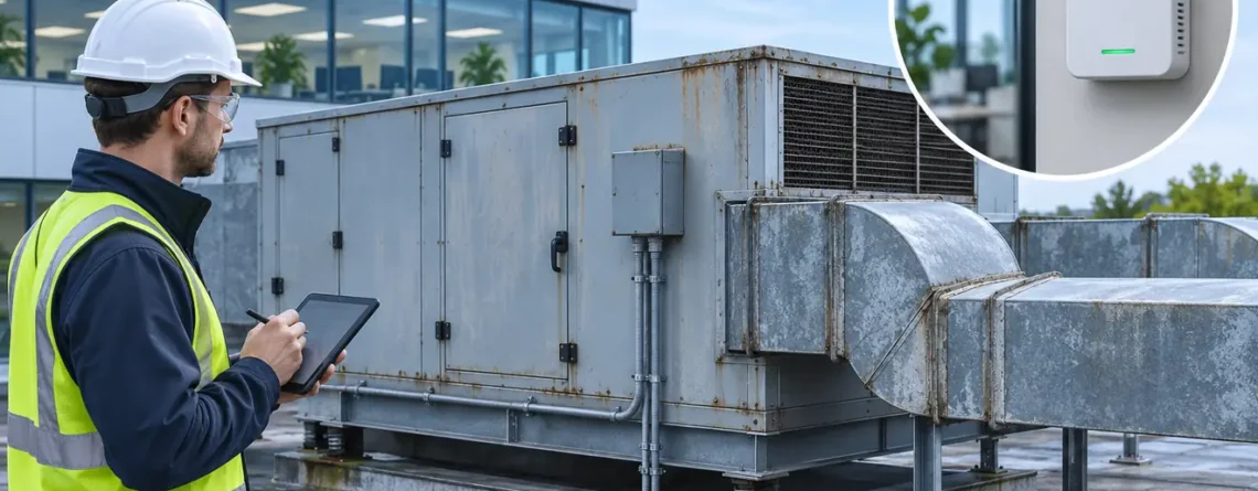
Add CO₂ monitoring to an existing HVAC system in stages. First map the actual outdoor-air path and choose representative spaces. Install and verify a read-only measurement, then observe it alongside occupancy and equipment operation. If the project needs CO₂-based ventilation control, confirm that the existing equipment can deliver the required outdoor airflow and that the approved sequence, fallback and functional tests are ready before allowing the new point to change HVAC operation.
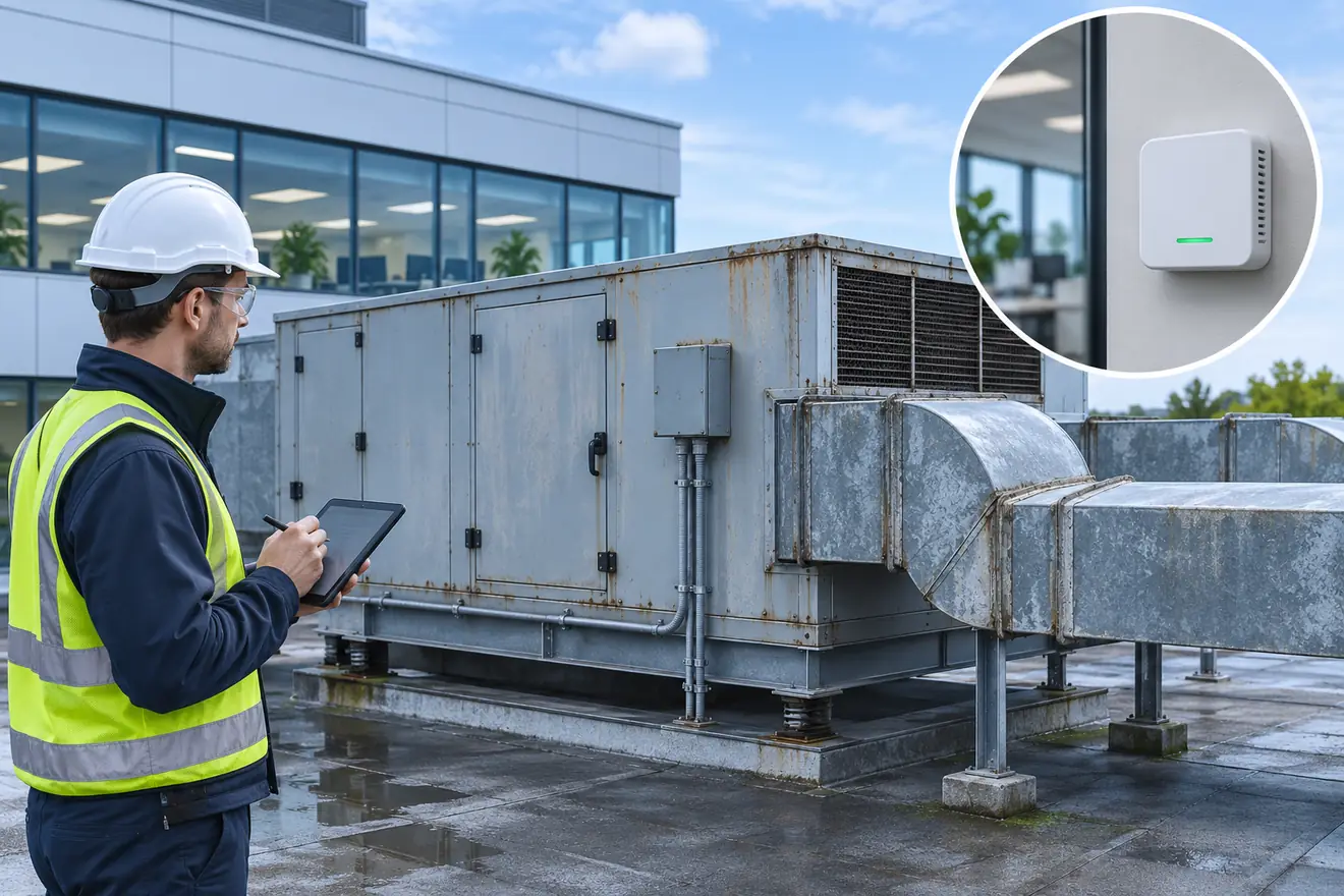
The existing air path and control authority determine what a retrofit can accomplish.
Start with the existing outdoor-air path
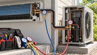
Find the actual source of outdoor air and how it reaches the occupied space. A supply diffuser confirms air delivery through a duct, but the air may come from recirculation, outdoor intake or a mixture. A wall-mounted unit may heat and cool recirculated air while a separate system supplies ventilation. A rooftop air handler may have a modulating intake that also serves an economizer sequence. A central unit may supply several zones through terminal units, each with different schedules and airflow. Check the route in the field and compare it with the current drawings.
The answer affects what an existing CO₂ signal could do. In a stand-alone room with no controllable outdoor-air path, monitoring can help identify when to investigate ventilation or review an existing procedure. It cannot create outside-air delivery. A central air handler with a working outdoor-air intake may be able to modulate intake, but its central damper alone does not resolve distribution among zones. A dedicated outdoor-air system can separate ventilation from sensible conditioning, but its terminal or central controls still need to deliver the specified air to each zone.
Review the design intent, the latest testing and balancing (TAB) report and any sequence changes since the building opened. Identify the required occupied operation, intended supply and outdoor airflow, expected fan modes, and existing authority for intake and terminal commands. For an existing building, drawings and balance reports may describe a previous configuration. Verify the installed controls, duct changes and actual operation before treating these documents as a present baseline. US Department of Energy Ventilation Assessment and Action Guide
| Existing arrangement | Useful first monitoring boundary | Question before considering control |
|---|---|---|
| Window or manual outdoor-air procedure | Occupied room and observed opening state | Is there an engineered controllable path at all? |
| Single-zone unit with modulating outdoor intake | Room CO₂, fan proof, intake mode and outdoor airflow | Can the equipment maintain the required intake over operating modes? |
| Multizone central system | Representative occupied zones, terminal airflow and central operating context | How will zone demand affect system outdoor air and distribution? |
| Dedicated outdoor-air system plus room units | Room CO₂ and dedicated ventilation delivery | Which controller owns outdoor flow, and can it prove each zone's delivery? |
| Recirculating fan coil or split system | Room CO₂ with independent ventilation context | Where does outdoor air actually enter, and which equipment can affect it? |
Choose a stage and define its authority
A local data logger or BAS read-only point is usually the simplest way to establish a baseline. Its purpose is to reveal patterns, provide context for complaints or compare times and locations. The room CO₂ value can be accurate and useful even if the existing system has no actuator that responds to it. Define who will review the trend and what investigation should follow a meaningful event.
An advisory stage can add a notification or trend-based recommendation without letting the CO₂ point change the equipment. For instance, staff could review a repeatable rise during meetings against the existing schedule and air delivery. An advisory should state the measurement, location, conditions and expected response owner. It should distinguish an unavailable sensor from an occupied-room observation, and it should be tested for both. Give users a clear action path so the notification produces operational evidence.
Enabled control is a project change. Determine the approved ventilation requirements and applicable project and jurisdiction conditions, then decide where the new demand signal is allowed to act. Identify how the signal coexists with required outdoor-air minimums, existing priorities, economizer operation, thermal and moisture constraints, and applicable equipment protection. An automatically written value should have a documented scope and an owner who can verify and restore operation. Use a reviewed change process rather than connecting a room output directly to a field actuator based on a ppm threshold alone.
| Escenario | Authority of new point | Gate to advance |
|---|---|---|
| Monitor-only | Read and trend | Representative placement, usable data and observed baseline |
| Advisory | Notify responsible staff | Context, quality and notification response verified |
| Enabled control | Affect approved demand or sequence | Design review, verified airflow, fault/recovery tests and operator release |
An advisory phase can be skipped when the project has the evidence needed to validate control and an approved implementation path. It is useful where a portfolio owner wants several weeks of comparable monitoring before changing equipment. The distinction is the authority of the point, not whether it appears on a sophisticated dashboard.

Inspect the installed controller and verify available inputs, compatible interfaces and existing control ownership.
Survey the spaces, equipment and interfaces
List the zones served by the equipment and identify which rooms have variable or concentrated occupancy. Note the approximate volume, intended occupancy, schedule, outdoor-air path and any local CO₂ sources. Focus the initial survey on spaces where a point can answer a meaningful question. A conference room with short dense meetings and a large open office can have different concentration patterns even when they share a mechanical system. A mixed return signal can conceal a high-concentration zone if the other return streams dilute it.
Review each candidate location for exposure to supply air, windows, doors, exhalation, thermal effects and servicing access. Portable comparisons can establish whether a convenient wall site behaves like representative occupied air. Photograph the exact location, record mounting height and label the zone. If a duct point serves a legitimate system-level question, identify whether it samples a particular return, mixed return or supply stream and document what conclusions the measurement can support. HSE guidance on using workplace CO₂ monitors
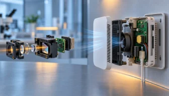
Review spare inputs and network capabilities in the existing controls. Determine whether the transmitter uses an analog output, supported network interface or a dedicated logger. Compare the expected transmitter output mode and scale with the receiver input. Confirm sensor power, installation environment, configuration access, supported device and firmware versions, and capacity to trend values at the needed resolution. If the controller exposes no appropriate live status, document how the BAS can distinguish bad data from an ordinary concentration.
Think through replacement before installation. A serviceable transmitter should have identifiable wiring or network mapping, a location record, a settings baseline and a documented comparison method. Verify the manufacturer's requirements for warm-up, maintenance and calibration. For any automatic baseline feature, confirm the conditions it expects and whether the occupied space actually encounters them. Long operating hours, limited vacancy or unusual background levels can affect the suitability of a baseline feature. Apply model-specific guidance rather than assuming the same behavior across transmitters.

The location and its intended sampling boundary should be recorded together.
Establish a monitoring baseline before changing the sequence
Trend room CO₂ together with occupancy context, the relevant equipment mode, fan proof and available airflow or position evidence. A monitor alone can reveal repeatability but may leave several explanations open. If the equipment schedule transitions at 07:30 and occupants enter at 08:00, capturing both events is more useful than comparing daily averages. Cover representative occupancy periods and environmental conditions. Record whether windows, partitions or portable units changed during the baseline.
Confirm that the installed sensor and its BAS reading agree under a documented comparison method. Check the physical measurement separately from controller scaling and trend delivery. Preserve the local reading, BAS reading, timestamps, status and reference condition. A live number can match while the historian uses a different point or stores too coarsely to show the events of interest. Test exports early enough to correct the trend settings before collecting a representative baseline.
A repeatable increase after meeting occupancy could be consistent with higher generation or limited dilution. Compare the time of the increase with the fan mode and ventilation delivery. An unexpected pattern during equipment downtime may instead indicate a schedule or occupancy exception. A central air handler may show normal outdoor intake while the terminal serving the room is below its intended flow. Treat the CO₂ trend as an investigative lead. Use measurement of the relevant airflow where the project requires it.
A baseline should record configuration as well as concentration. Note the operating schedules, thermostat and economizer modes, signal averaging and any outstanding HVAC deficiencies. Otherwise a later comparison could ascribe a change to the new sensor or sequence when occupancy, weather or a separate repair changed. If significant repairs are needed to establish the intended existing operation, document the before and after states separately. This keeps a monitoring improvement from being mistaken for an airflow improvement.
Coordinate control authority and failure behavior
If the project decides to use CO₂ for demand-controlled ventilation (DCV), specify what the CO₂ input requests and how the existing equipment executes it. The sequence may adjust a zone demand, outdoor-air intake or another project-defined control variable. Identify the effective command owner and how it handles other priorities. A room sensor should not silently become authoritative over unrelated protection or ventilation requirements simply because its output is present on the network.
The ASHRAE ventilation chapter describes occupancy-based reset and explains why air-handler and zone behavior matters, especially in systems with variable primary airflow. In a multizone project, a demand seen in a conference room may need both a zone airflow response and a coordinated outdoor intake change. The project designer should establish the relevant minima, fan and damper ranges, distribution method and any constraints imposed by the system and adopted requirements. ASHRAE Fundamentals chapter on ventilation and infiltration
An equipment application note from Amphenol Telaire describes examples involving existing direct digital control (DDC), rooftop systems and variable air volume (VAV). Those arrangements illustrate plausible interfaces. The installed outdoor-air path and approved operating requirements determine what the project can actually implement. Amphenol Telaire application note on using CO₂ for zone ventilation
Write the failure behavior before activation. If the sensor is unavailable, stale, outside its valid range, under approved test or warming up after power returns, identify what the sequence should use instead, what should be logged and who should be notified. An automatic return to CO₂ control may require restored quality and a defined recovery check. Document how a temporary operator override is visible, how it expires or is removed, and which state should be present after any test. The fallback must come from the approved design and project requirements.
Consider what a small pilot can prove. A single zone with an independent outdoor-air path may demonstrate point integration, fault behavior and delivery in its operating envelope. It says little about aggregation logic on a central multizone unit. Select representative conditions for each equipment family rather than extending results across unlike systems. Keep the limits of the verified scope with the handoff.
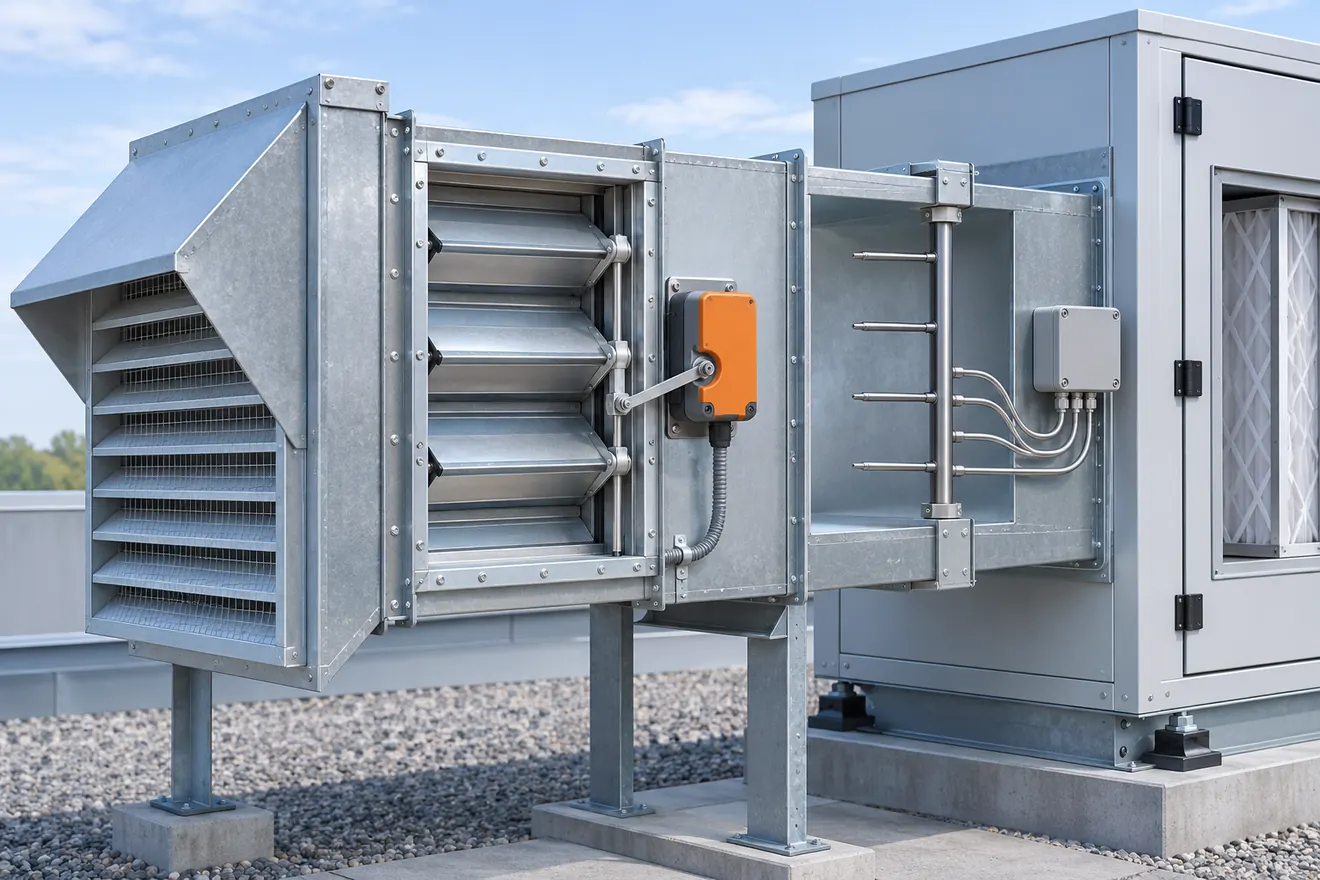
The actuator changes the air path. A separate measurement can help establish the flow delivered under test conditions.
Verify the retrofit at three boundaries
The first boundary is measurement. Verify that the installed sensor represents the intended air and that its reading is reasonable under the documented comparison conditions. Record installed model and configuration, reference information, observed values and agreed tolerance. Test any point loss or stale condition relevant to use. The monitor-only phase can be accepted at this boundary and the data boundary below without a control change.
The second boundary is data delivery. Compare the local output with the receiving point, readout, history and any advisory. Verify engineering units, update behavior, timestamp and quality. If a point is supplied to a local or supervisory sequence, check the exact input the sequence sees. A test from the graphics layer can miss a different source used by the controller. Preserve the authorized test method and whether a value was measured, simulated or temporarily selected.
The third boundary is functional ventilation performance. An approved test should compare expected sequence response, effective command, proved equipment state and actual airflow where required. Verify normal low and increased demand under applicable modes, then test invalid inputs and restoration. A damper percentage is not a measured volume flow. Check the project method for verifying intake and delivery at the relevant boundaries. In a multizone system those boundaries may include both the air handler and affected terminals. ASHRAE Applications chapter on controls design and application
Consider a hypothetical existing office with one rooftop unit serving a training room and two adjoining offices. The training-room CO₂ trend rises during dense classes. The operator sees the unit's damper command, but the existing balance report predates duct alterations. Monitoring can be accepted once the room point, its context and history are verified. Enabling a control change requires identifying which zones share the unit, confirming minimum and achievable outdoor airflow, and testing how the training-room request affects distribution and all applicable operating modes. If airflow at the needed conditions cannot be verified, record the gap and keep the monitoring project separate from the proposed control work.

Acceptance records distinguish the data added to the BAS from verified changes to system operation.
Give the operator a repeatable handoff
The turnover package should include an as-built equipment and zone map, sensor locations, model and serial information, settings, point names and units, controller backup or revision, reference comparisons, trend exports and the scope of accepted use. For an approved control change, include the final sequence, valid and fallback behavior, functional tests, unresolved conditions and the rollback or restoration procedure. Identify the people responsible for the measurement point, the HVAC equipment and review of any advisory.
Walk through one normal trend, one invalid input and one site-specific follow-up. Show where to distinguish a disabled sensor from a quiet room. Confirm who can review airflow evidence, change settings and clear supervised overrides. The operation team should know whether the new information is diagnostic only, advisory or permitted to drive the sequence.
Establish an activation decision before a control pilot
Write a short gate record for the proposed sequence. It should identify the equipment and affected spaces, the approved ventilation criteria, what the new point can change, and the independent evidence of delivery. Include the configuration revision that will be tested, the authority responsible for accepting it, and the scope of any temporary operating conditions. A contractor's checkout and a control designer's approval cover different parts of that decision.
| Gate evidence | What to look for | When to hold activation |
|---|---|---|
| Outdoor path and distribution | Verified route and current documentation | Supply path or served zone still uncertain |
| Sensor and BAS point | Representative site, valid reading, history and quality | Point is unstable, mislocated or cannot identify stale data |
| Respuesta del sistema | Effective command, proof and airflow at required conditions | Position changes with no verified outdoor-air response |
| Sequence interactions | Normal, constrained and transition modes reviewed | Economizer or another required priority is unaccounted for |
| Failure and recovery | Approved fallback, status and restoration verified | Input loss leaves equipment response undefined |
| Handoff | Responsible owner, evidence and rollback access | Staff cannot identify approved state or retrieve records |
A rooftop unit example illustrates how the gates differ. Imagine the survey finds a spare analog input and a working economizer actuator. That confirms a possible connection and a moving component. The team still needs to verify the correct signal range and whether the occupied ventilation sequence and actual outdoor-air delivery operate as intended at relevant fan states. If the approved minimum airflow cannot be maintained at a lower fan speed, adding a faster sensor will not resolve the underlying limitation. Complete the read-only monitoring scope if it is verified, then route the equipment issue to the appropriate project owner.
Another hypothetical system uses a central ventilation unit plus local heating and cooling terminals. The team identifies that the local thermostat controller has a free input but the ventilation controller is elsewhere. Adding the CO₂ transmitter to the local thermostat could create useful trend data, but any future ventilation demand needs a documented path to the controller that actually owns it. Confirm that any cross-controller use conveys data quality and age. If the link is unavailable, the agreed fallback should operate at the receiving controller. The design cannot assume that a value arriving at a supervisory display will also reach the device responsible for outside air.
Test the interactions that matter in this building
A clear sequence test compares expected and actual behavior under documented conditions. Review normal occupied operation first. Verify the point and the effective control request, then compare mechanical response and airflow where required. Under the relevant range of fan operation, check how the ventilation system establishes its required delivery. The fan may maintain a lower speed under partial load, changing intake behavior at the same damper angle. An approved test at one speed can leave that question open at another speed.
Next consider relevant operating transitions. An economizer may increase outdoor intake for temperature control, while a different mode limits operation to a minimum or disables equipment according to the approved sequence. Document how the request is arbitrated in each applicable condition. Include status that distinguishes an active CO₂ request from one limited or superseded by another mode. In a building with significant exhaust or specialized pressure relationships, refer to the applicable design and test criteria. Adjusting outdoor air independently may affect the balance that those systems depend on.
Verify the agreed unavailable state using the project procedure and capture the effective behavior, not just an alarm on a screen. If the reading remains cached during a communications loss, confirm that it becomes unusable for the sequence within the specified conditions. When the transmitter restarts, check that warm-up and recovery are handled as specified. For each test, save evidence that temporary changes have been removed and normal approved operation is restored. State which equipment or seasonal conditions could not be tested and where follow-up is recorded.
Decide how a portfolio rollout will stay comparable
If the first installation is a pilot, name what counts as success before the trend begins. One useful deliverable is a complete occupied-period dataset that can be tied to equipment and occupancy context. Another is a demonstrated installation and comparison method that staff can repeat. For a control pilot, the criteria also need the scope and conditions of functional verification. Record any meaningful differences in installation time, data loss, repairs and operator workload. Avoid generalizing a short observation window into a performance claim for dissimilar buildings.
Standardize the fields that allow later comparisons, such as room identity, monitoring location, equipment association, time source and whether the point is monitor-only. Preserve building differences rather than forcing every installation into one physical design. A lightly occupied office with continuous ventilation and a training room used in short bursts may require different logging context, representative positions and review windows.
Include a maintenance check after initial operation. Review whether the installed point remains accessible, whether the trend and quality are available, and whether known occupancy or equipment changes altered its intended interpretation. If the device or configuration is replaced, preserve the prior trend period and verify the new state. Sensor1stop's guide to CO₂ monitor accuracy specifications explains how to read a manufacturer accuracy statement when comparing a field monitor or replacement. Use the approved field comparison method and the installed system's requirements when making an acceptance decision.
Preguntas frecuentes
Can monitoring help if my existing HVAC system has no BACnet?
Yes. A suitable logger or compatible hardwired input can support a monitoring baseline. The project still needs representative placement, valid readings, usable timestamps and an agreed process for reviewing the data.
Can I use one return-air monitor for the entire building?
It can describe the air sampled at that return if the location and operating conditions are suitable. A mixed return can obscure zone differences. Use representative zone measurements when the question concerns particular occupied spaces.
Does a CO₂ monitor prove required outdoor airflow?
It can provide contextual evidence about concentration and dilution. Verifying required outdoor airflow needs the approved measurement or verification method and knowledge of the system's operating conditions and delivery boundary.
Do I need to change ventilation controls to benefit from CO₂ data?
No. A read-only trend with occupancy and equipment context can identify conditions that deserve investigation. A controls change is a separate decision with its own design and verification requirements.
When can I call the retrofit accepted?
Define acceptance for the stage being delivered. For monitoring, verify placement, measurement, data and operator access. For enabled control, also verify the approved sequence, airflow performance where required, fault recovery, restoration and handoff.






Deja una respuesta