
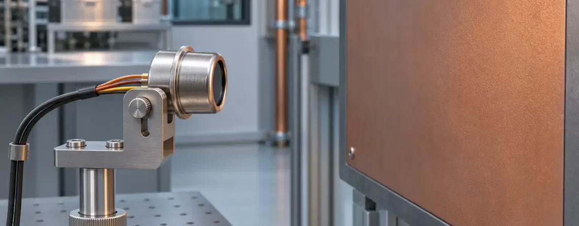
Choose a thermopile infrared temperature sensor by first defining the surface you need to measure, then checking whether that surface fills the optical response area, whether its emissivity is sufficiently known, and whether the sensor remains thermally stable inside the finished enclosure. Finally, validate the complete assembly over the intended target and sensor temperatures. A digital temperature output and a factory calibration do not remove these application conditions.
This approach is useful for moving products, inaccessible machine surfaces and other situations where contact probes are inconvenient. It also identifies tasks for which a contact temperature sensor is the better starting point. The important purchase is a measurement system that answers the process question, including its optics, mounting, compensation and validation.
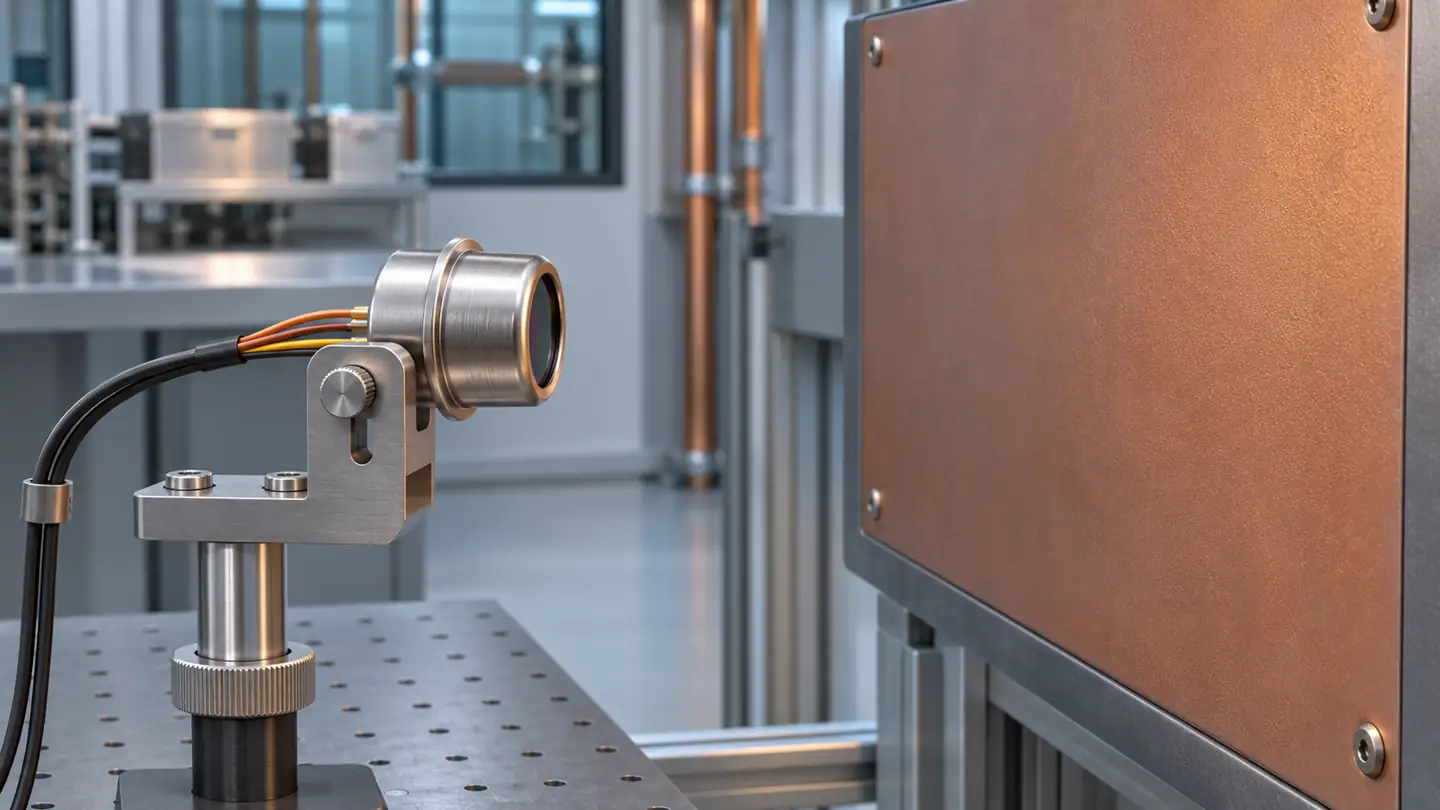
The sensor views radiation from a surface across an air gap. The illustration shows equipment placement; it does not represent a particular product or a measured temperature.
Define the temperature before choosing the sensor
A thermopile infrared thermometer estimates the temperature associated with radiation arriving from its viewing direction. For an opaque target with suitable optical coverage, this can represent the visible surface temperature. It does not directly measure the air between the target and sensor or the temperature deep inside the object.
That distinction changes the sensor choice. A bearing housing surface can be relevant to a condition trend, but its temperature is not automatically the bearing race temperature. A package exterior can be warmer or cooler than its contents during a process transition. A pipe exterior can differ from fluid temperature because of wall resistance, insulation, airflow and changing flow conditions. Any relationship to an internal temperature requires separate evidence for that assembly and operating state.
Start with a small requirements worksheet. Record the coldest and hottest surface conditions, but also the acceptable error near the decision point. A broad measurement range is less useful than predictable behavior where a controller changes state.
| Requirement | que grabar | Why it affects selection |
|---|---|---|
| mensurando | Named surface, location and process state | Prevents confusing surface, air and internal temperatures |
| Target | Material, finish, coating and minimum dimensions | Sets emissivity uncertainty and optical coverage |
| Geometry | Minimum/maximum distance, angle and positional tolerance | Determines which surfaces contribute radiation |
| Momento | Required decision delay and target dwell time | Constrains detector response, filtering and communications |
| Sensor environment | Enclosure temperature, airflow, nearby power components | Determines thermal disturbances and compensation needs |
| Optical protection | Window, opening, dust, condensation and cleaning | Changes transmission and long-term stability |
| Acceptance | Permitted error and conditions for rejecting a reading | Provides a meaningful qualification target |
If the actual requirement is air temperature in a duct, select an air-temperature measurement arrangement. An infrared sensor looking into the duct will generally respond to the surfaces in its view, not provide a direct replacement for an appropriately installed air probe.
Understand the detector-to-temperature chain
Infrared radiation absorbed by a thermopile warms a thermally isolated sensing region relative to reference junctions. Multiple thermocouples convert that difference into an electrical signal. A usable temperature measurement then requires signal conditioning, knowledge of the sensor's thermal state and a relationship between received radiation and the target. Nippon Ceramic's thermopile explanation describes the membrane, absorber and thermocouple arrangement.
A raw thermopile element and a digital infrared thermometer therefore create different integration tasks. With an analog element, the designer must provide suitable amplification, digitization, reference-temperature measurement and conversion. A digital device can combine several of those functions. Its object-temperature register remains conditional on the scene and the assumptions used by the conversion.
The device's reported ambient or die temperature deserves particular attention. In this context it supports compensation for the sensor's own thermal condition. It should not be assumed to equal room air temperature, enclosure wall temperature or the temperature of the target's reflected surroundings. Those are different physical quantities, even when they happen to agree after a long stabilization period.
For selection, ask what is available to the host: raw signal, package or die temperature, calculated object temperature, diagnostic information and configurable filtering. Access to intermediate readings can make qualification easier. It helps distinguish an optical change from package warming instead of reducing every problem to an unexplained temperature offset.
Treat emissivity and reflected radiation together
Emissivity describes emission relative to a blackbody under the relevant conditions. It is not simply a permanent number attached to a material name. Finish, coating, oxidation, wavelength and viewing conditions can matter. A polished metal part and a coated version of the same part may require different measurement strategies.
Radiation arriving from an opaque surface contains both the surface's own emission and radiation reflected from its surroundings. A low-emissivity surface can therefore produce a reading strongly influenced by nearby hot equipment or a cold background. The sensor may be operating correctly while the inferred surface temperature is unsuitable for the decision.
FLIR's official measurement-parameter guidance distinguishes emissivity, reflected temperature, atmospheric conditions and external-window compensation. These radiometric distinctions apply to understanding the scene; the specific settings available depend on the chosen sensor or instrument.
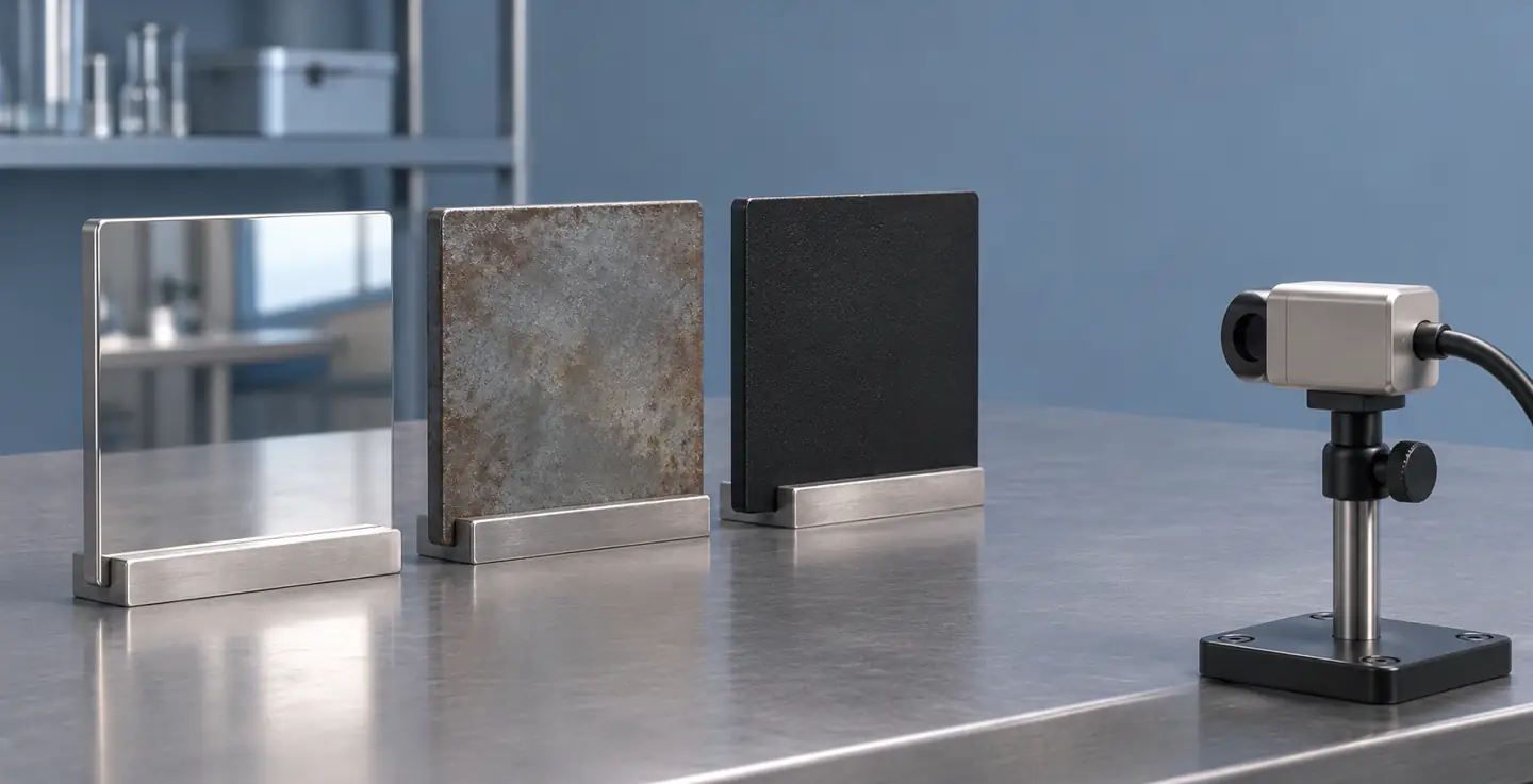
Surface finishes can behave differently in infrared measurement. The illustration assigns no emissivity values or temperatures to these samples.
A material table is a starting point
A generic emissivity table can help identify a difficult target, but it cannot prove the value for a particular production surface. Identify whether the part is painted, plated, oxidized, wet, oily or subject to abrasion. Record which of those states are allowed during operation. If the finish changes through the process, one coefficient may not remain adequate throughout that process.
A useful qualification comparison is the same representative target under deliberately varied surrounding conditions, while an independent reference tracks the target. If an IR reading changes with the surroundings more than the reference supports, investigate reflection before changing the calibration. This is a proposed diagnostic comparison, not evidence that a specific material will pass it.
Changing viewing angle can also change reflected contributions and the effective surface area. Keep the production angle within the range evaluated. A fixture that holds the distance constant but allows substantial tilt has not fixed the measurement geometry completely.
Reference patches have conditions
A stable, suitable high-emissivity patch can sometimes provide a better-defined viewing surface. However, a patch must tolerate the process, adhere reliably, be large enough and reach a temperature representative of the underlying surface. A thick coating, loose tape or insulating adhesive can introduce its own thermal difference.
The patch approach also changes the measurand: the sensor now views the patch surface. Establish whether that surface follows the process location closely enough in steady conditions and during transitions. Do not infer that a patch suitable for a slow laboratory comparison will remain suitable on a rapidly moving or chemically exposed product.
For transparent or partly transmitting targets, the simple opaque-surface interpretation is incomplete. Radiation from behind the target can contribute. Thin films and windows require attention to wavelength-dependent transmission; visible opacity is not proof of infrared opacity.
Match field of view to the smallest target
A single-element thermopile does not isolate an arbitrarily small point. Its angular sensitivity distributes weight across the scene. A large target close to the axis can dominate the signal, while a small target can be mixed with a conveyor, housing or other background.
Manufacturers do not necessarily define field of view in the same way. Some quote a response threshold; others provide energy coverage or distance-to-spot information. The TI TMP006/B datasheet is a useful example of distributed angular response. A quoted angle should never be treated automatically as a boundary outside which radiation contributes nothing.
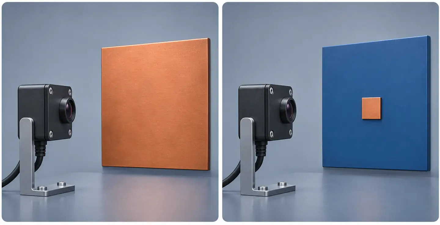
The smaller target leaves more background available to influence a single-element measurement. No optical cone, response threshold or exact spot diameter is implied by the illustration.
A preliminary geometry calculation
For an ideal cone with full angle θ and a perpendicular target plane at distance L from its apex, the geometric diameter is:
D = 2 × L × tan(θ / 2)
For a hypothetical 20° full angle at 100 mm distance, D is approximately 35.3 mm. At 200 mm it becomes approximately 70.5 mm. This calculation describes the assumed geometry only. It does not establish the target diameter needed for a specified temperature accuracy, because real optical response has a distribution and the optical reference point may differ from the assumed apex.
Use the manufacturer's definition, response curves and recommended target-fill conditions to turn geometry into a qualification requirement. Include alignment tolerance and the smallest target, rather than selecting against the largest sample placed perfectly on axis. A small hot target surrounded by a cooler belt is a particularly useful worst-case configuration to consider.
A mixed scene should not be interpreted as the arithmetic average of surface temperatures. The detector combines radiation with angular and spectral weighting; the temperature conversion is nonlinear. Moving closer may reduce background contribution, but it must remain compatible with mechanical clearance, the optical design and the sensor's thermal environment.
Distance-to-spot is not a targeting aid specification
If an instrument includes a visible aiming mark or laser, verify how that mark relates to the actual measurement area. An aiming feature does not itself define the infrared optical response. For embedded sensors without an aiming feature, provide a repeatable mechanical datum so that optical alignment can be inspected during assembly.
Likewise, placing a narrow tube ahead of a wide-angle sensor does not automatically create a calibrated narrow-angle thermometer. The tube may obstruct radiation, emit its own radiation and develop temperature gradients. An added aperture or baffle becomes part of the optical and thermal assembly that needs evaluation.
Include dwell time, filtering and communications
A moving target must occupy the useful measurement region long enough for the required estimate. Detector response, internal conversion, digital filtering, polling and controller logic all contribute to delay. A fast bus transaction cannot compensate for a slowly settling optical signal.
Consider a hypothetical part with 60 mm of useful length in its direction of motion, travelling at 0.5 m/s. Its nominal passage time is 0.12 seconds. The interval in which the complete useful optical footprint sits inside that part can be shorter. A design requiring several heavily averaged readings must fit inside that shorter interval, or use a different optical arrangement or sensing method.
Ask whether the device's response specification describes a time constant, a settling percentage, an output update interval or a filtered temperature response. These quantities are related but different. Evaluate the actual configured device rather than combining a fast detector specification with an unrelated slow filtering option.
For a controller, also define behavior between targets. A background reading should not silently become a product-temperature reading because the software receives a fresh register value. Position information, suitable triggering or a validated scene rule may be necessary to distinguish useful samples from gaps.
Keep the sensor thermally stable inside the enclosure
Compensation is most effective when the measured sensor temperature represents the thermal state relevant to the detector. Uneven heating creates a harder problem. A nearby regulator can warm the PCB while airflow cools the sensor cap; touching the enclosure or opening a hot access panel can create another transient.
Melexis's thermal and mechanical design application note identifies electronics heating, airflow and rapid environmental changes as integration concerns. Its package-specific recommendations include thermal separation and attention to the optical opening. Apply those recommendations alongside the exact device documentation.
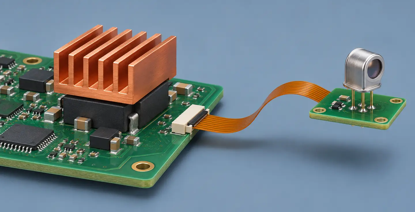
Separating the sensor from power electronics can reduce unwanted heat paths. This conceptual arrangement is not a dimensional PCB layout or a guarantee of thermal performance.
Give heat-producing components an escape path that does not depend on conduction through the sensor region. Consider whether the sensor needs a separate board, thermal isolation features or a carefully designed shield. Any shielding must leave the required optical response unobstructed and avoid becoming an uncontrolled warm surface in view.
There is a tradeoff between isolation and equilibration. Increasing thermal mass can reduce the effect of fast disturbances while also changing how long the assembly takes to settle. A universal warm-up delay cannot be inferred from the technology name. Determine a valid settling condition for the finished product and the disturbances it will experience.
During qualification, hold a reference target stable while changing electronics operating states. Include communication activity, illumination, heaters, chargers or other loads relevant to the product. Log the IR reading and available sensor-temperature channel together. A reproducible shift after a power-state change indicates an integration issue worth resolving before fitting a cosmetic offset.
Select a protective window as an optical component
A cover that looks transparent to the eye is not necessarily suitable for the sensor's infrared band. Conversely, a visually dark material may transmit useful infrared wavelengths. Select from spectral transmission data over the sensor response and intended target conditions, including the actual thickness and coatings.
Adding a window introduces more than attenuation. The window can also emit and reflect radiation, and contamination can change the effective path. An enclosure tested without its final window is therefore not the complete optical system. FLIR's external-window compensation guidance identifies the protective optic as a separate measurement parameter.
| Window question | Evidence to request or establish |
|---|---|
| Does it transmit in the relevant band? | Spectral data for the actual material, coating and thickness |
| Does the clear opening cover the optical response? | Assembly geometry with tolerances and device response information |
| What happens as it warms? | Assembled-system evaluation over expected window temperatures |
| Can dirt, water or condensation accumulate? | Inspection and maintenance provisions, plus invalid-reading behavior |
| Can cleaning alter it? | Compatibility information and repeatability after the intended cleaning method |
| Will replacement change the result? | Defined replacement specification and verification requirement |
Do not automatically divide a temperature reading by a transmission factor. Optical losses act on radiation, while temperature conversion is nonlinear and the window can contribute its own radiation. Use the supported compensation model or an assembled-system calibration suitable for the device.
If an air purge is proposed to keep the window clean, evaluate its thermal effects as well as its cleaning benefit. Airflow can change the target's surface temperature or disturb the sensor housing. A cleaner optical path is valuable only if the resulting measurement still represents the defined process condition.
Compare complete variants, not headline accuracy
A product family can contain different supplies, optics, thermal-gradient compensation and interface options. Record the complete ordering code and datasheet revision. The current Melexis MLX90614 datasheet, for example, separates variants and provides conditional accuracy information. A family-level feature list is insufficient to establish performance in a finished product.
Resolution, repeatability and accuracy answer different questions. Resolution concerns the size of reported increments. Repeatability concerns the spread under repeated conditions. Accuracy concerns agreement with the reference under stated conditions. A steady display with many decimal places can still contain substantial systematic error.
Compare target-temperature range with sensor operating range separately. A device can view a hot object while its own electronics must remain much cooler. Check both axes of any accuracy plot, including whether the required object temperature falls outside the region associated with the headline specification.
For an analog element, also check signal level, noise assumptions, thermistor characteristics and conditioning requirements. For a digital device, check conversion settings, interface levels, error flags and how custom calibration or emissivity parameters are stored. Verify that a configuration survives the power cycles relevant to the product.
Build a qualification plan for the final assembly
Calibration establishes a relationship to reference conditions. Validation asks whether the resulting assembly meets the intended requirement on conditions it must actually encounter. Preserve that distinction: a calibration fit can look excellent on its own input data while failing on other surfaces or after the enclosure warms.
The legacy TI TMP007 Calibration Guide, SBOU142 provides a useful method: define the environment, obtain reference object temperature with sensor data, consider die-temperature variation and verify the calibration. The method is relevant as engineering background; it is not a recommendation about current TMP007 availability.
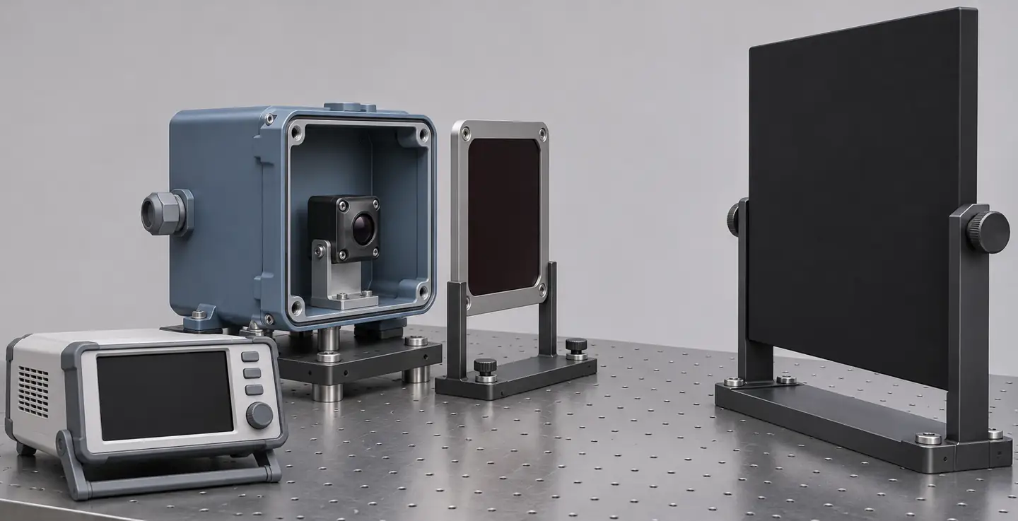
Qualify the sensor with its actual optical protection and mechanical arrangement. The bench is illustrative and contains no test results.
Separate two questions
First, determine whether the instrument assembly performs as intended against a suitable radiometric reference under controlled geometry. Second, determine whether representative application surfaces can be measured reliably. A reference source with well-defined radiance does not prove the emissivity or reflected environment of the production target.
The reference must have suitable uncertainty and stability for the desired acceptance limit. A contact reference on a real part also needs careful interpretation: attachment, thermal contact, local gradients and response time can make it disagree with the viewed location without either instrument having a simple constant error.
For a proposed qualification, select conditions that challenge the assumptions rather than collecting many nearly identical room-temperature readings.
| Condition varied | Question answered |
|---|---|
| Target temperature across the useful range | Does conversion remain acceptable near decisions and extremes? |
| Sensor/enclosure temperature | Does compensation remain useful over the installation environment? |
| Distance, alignment and smallest target | Does background contamination remain within the requirement? |
| Representative surface finishes | Does the chosen emissivity treatment cover allowed production variation? |
| Nearby hot/cold surroundings | Are reflected contributions controlled sufficiently? |
| Start-up, load changes and airflow | Is there a transient period when readings should be rejected? |
| Clean, aged and replaced optical protection | Is maintenance compatible with repeatable measurement? |
Keep calibration conditions within the documented model and avoid assuming that a fit supports unlimited extrapolation. Reserve independent conditions for validation. Include representative units if the result must transfer across production, and repeat assembly where mounting tolerance could matter.
Keep a useful record
Log the reference reading, reported object temperature, available die or package temperature, distance, target identity, finish, window identity, firmware settings and time since disturbance. For moving parts, include position or timing information. These records allow a later change to be compared with its real cause instead of with memory of a successful demonstration.
Report bias, spread and transient behavior separately. If a limit is exceeded, record the condition and whether the reading can be flagged as invalid. A narrow acceptance band has little practical value if normal operating changes routinely produce unrecognized errors outside it.
Apply the selection sequence to real design questions
The following are hypothetical design examples, intended to show how requirements change the choice.
Coated parts on a conveyor. Begin with the smallest coated area and the fastest movement. Choose geometry that keeps the useful response inside the part for sufficient time. Validate coating variations, gaps between parts and nearby heaters. A wider view may simplify alignment while adding belt radiation; the correct balance depends on the acceptance requirement.
A reflective machine housing. Establish whether the actual surface finish is controlled. Check sensitivity to hot equipment and changing viewing angle. If a qualified patch is possible, evaluate its thermal behavior. If neither emissivity nor reflection can be controlled sufficiently, a contact sensor may provide a more defensible measurement at the required location.
A sensor inside a compact powered enclosure. Check cold start, full processing load and changing ventilation with a stable reference target. A device with suitable nominal accuracy may still need a different mounting location, board arrangement or stabilization rule. The decision is driven by the assembled thermal behavior rather than the number of digits in its register.
Diagnose the pattern before changing calibration
| Patrón observado | Plausible causes to investigate | Useful distinguishing check |
|---|---|---|
| Reading changes with distance | Target underfill, alignment, window geometry | Compare with a sufficiently large uniform reference |
| Reading changes as surroundings change | Reflection, background in view, window heating | Hold target stable and vary one surrounding condition |
| Drift follows electronics warm-up | Sensor gradients or changing enclosure temperature | Log sensor-temperature channel and power state |
| Short moving parts read differently from stationary parts | Insufficient dwell, filtering, trigger timing | Compare configured response with usable occupancy time |
| Cleaning or window replacement changes readings | Optical transmission or surface damage | Inspect assembly and repeat reference verification |
| One offset works only near one temperature | Model, emissivity or calibration range mismatch | Examine error across target and sensor temperatures |
These patterns suggest investigations, not unique diagnoses. More than one mechanism can occur simultaneously. Correct geometry and thermal design before adding coefficients intended to conceal an unstable scene.
Preguntas frecuentes
Can a thermopile measure room air temperature?
Its infrared channel primarily responds to radiation in its view. A reported ambient channel commonly describes the device's own thermal condition for compensation. Use an appropriately arranged air-temperature sensor when air temperature is the measurand.
Does factory calibration mean no application calibration is needed?
It can reduce integration work, but the finished assembly still needs validation. Added windows, changed optics, uncertain emissivity and sensor gradients can all matter. Whether additional calibration is needed depends on the device's documented conditions and the application requirement.
Is a narrower field of view always better?
It can reduce background contribution for a small target, but it also demands sufficient alignment control. Compare complete optical response, required distance and production tolerances. A nominal angle alone cannot decide the measurement quality.
Can one emissivity setting cover every metal part?
That assumption is usually too broad to establish a reliable measurement. Surface finish, oxidation, coating and contamination may differ. Define the permitted surfaces and validate them under the relevant reflected surroundings, or choose another measurement arrangement.
Will averaging fix a wrong temperature?
Averaging can reduce some random variation, with a delay tradeoff. It does not remove systematic error from an unsuitable emissivity setting, background radiation, optical contamination or a thermal gradient. Determine the error mechanism before increasing filtering.
Does a surface reading establish internal or core temperature?
Only if an appropriate relationship has been established separately for that object and operating condition. Thermal gradients and changing heat transfer can break an assumed relationship. For this selection task, label the output as the viewed surface temperature and evaluate any further inference independently.










Deja una respuesta