
Free-space radar is usually the first candidate when the tank headspace changes with heating, solvent vapor or condensation, or when a narrow beam can clear internal equipment. Ultrasonic remains a practical choice for calm liquid in a vented tank with a predictable gas path, a clear mounting position and enough headroom at maximum operating level. For either technology, the decision comes down to whether the installed transmitter can follow the required liquid surface across the whole operating range. Persistent foam, a recessed nozzle or a misleading reflection can defeat either method.
Start with the tank drawing and the process conditions. At the highest normal level, check the available distance from the instrument's measuring origin. At the lowest normal level, check the longest path and what lies beside or below it. Then ask how the return changes while the tank fills, drains, mixes or heats. Those three checks tell you more than comparing the nominal maximum ranges of two transmitters.
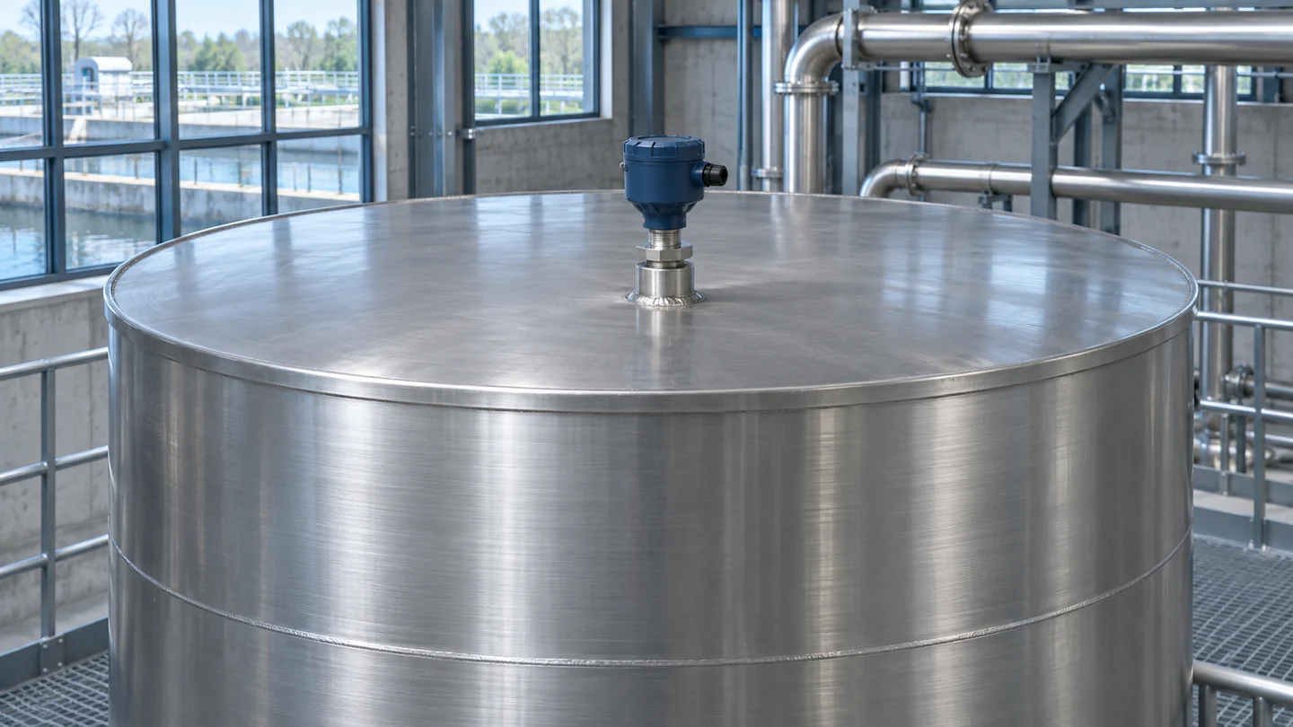
An overhead transmitter measures distance along its installed path. The roof connection, the liquid surface and the space in between determine which echoes it can use.
What the transmitter measures
Both methods start with the gap between an instrument reference and a reflecting surface. In a vertical installation, level above a chosen tank datum equals the height of that reference above the datum minus the measured gap. As liquid rises, the gap decreases and the reported level increases. A nozzle flange and an antenna face can sit at different elevations. Use the measuring reference in the exact mounting drawing so that the reference elevation and reported distance have the same origin.
An ultrasonic transducer sends a pulse of sound through the gas above the liquid. A portion of the pulse reflects from the liquid surface and returns. For a uniform gas path, distance equals the round-trip time multiplied by the speed of sound and divided by two. The controller needs both a usable return and a suitable sound velocity for the gas through which the pulse traveled. A valid looking echo can yield the wrong distance if the assumed velocity is wrong. Siemens SITRANS LUT400 operating instructions
A free-space radar antenna transmits microwaves through the space above the liquid. In a frequency-modulated continuous-wave design, the transmitter sweeps the frequency, so a delayed return differs in frequency from the signal currently being sent. The electronics use that difference to estimate distance. A strong dielectric contrast between the gas and liquid generally gives a stronger reflection, all else equal. The antenna, the surface and signal processing determine how much of that reflection the instrument can use. Guided-wave radar sends its signal along a probe into the vessel and has a different installation and measurement path. Emerson Rosemount 5408 radar documentation
Before comparing instruments, define the output. Distance may be useful for diagnostics, while the operator may need liquid height above an outlet or percent of an operating span. A reading of 50% of the height range in a horizontal cylinder or a vessel with a conical bottom need not represent 50% of its capacity. For volume, use the applicable tank calibration or geometry and retain the level trend so a change in the volume calculation can be distinguished from a change in the measurement. Where the task is simply to detect liquid at one position, a point switch is another class of instrument. Endress+Hauser continuous level measurement primer Sensor1stop water level sensor overview
How vapor, foam and condensation change the reading
A tank can develop more than one problem at the same time. Warm vapor can change the sound velocity along the path. Entrained droplets can reduce the usable return. A wet film or deposit can change the behavior of the transducer face or antenna. Surface foam can introduce another reflecting interface. Describing the state as “wet” or “steamy” leaves out the information needed to tell these effects apart.
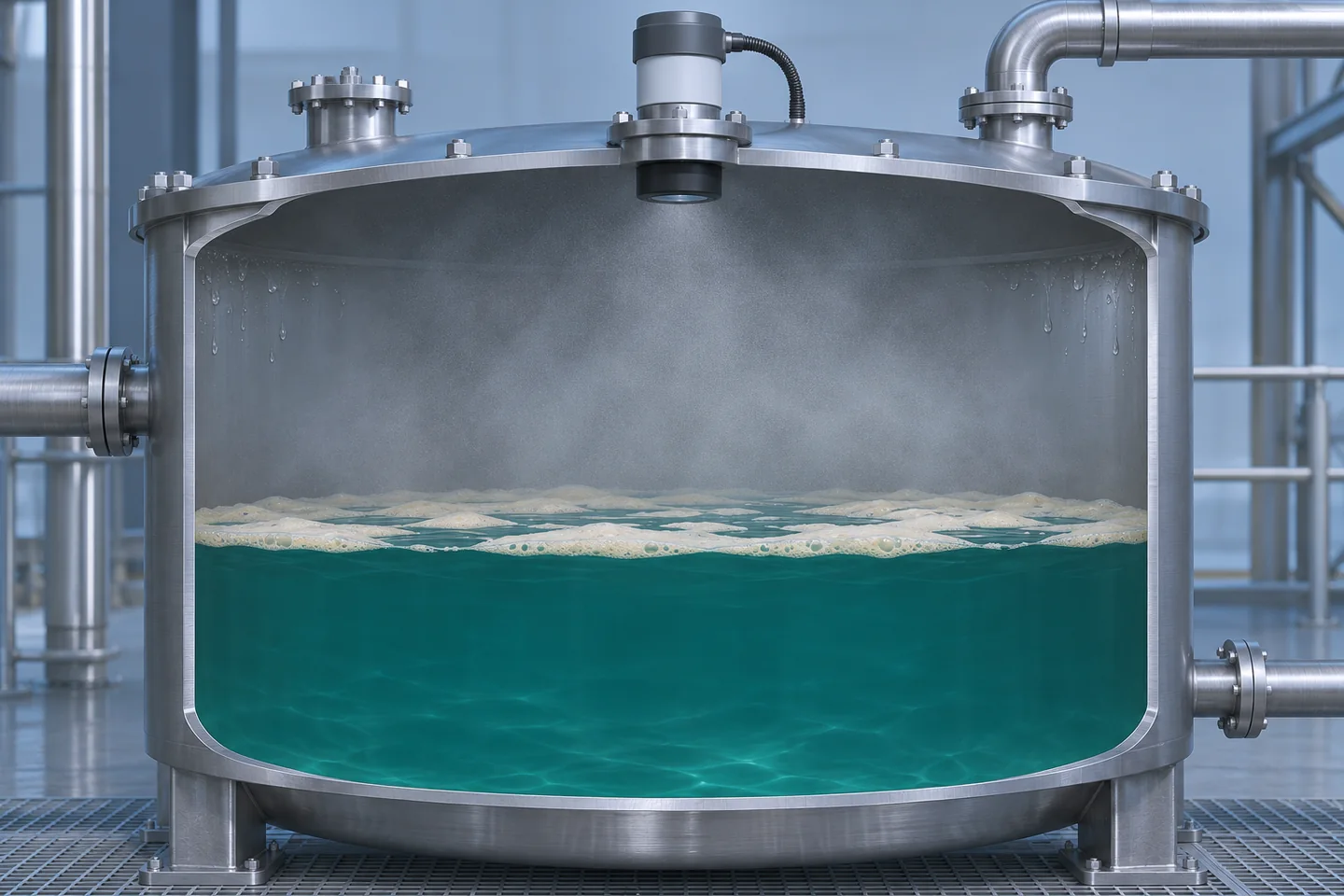
Foam at the surface and moisture in the space above it act at different points along the measurement path. This cutaway shows where those conditions occur.
Temperature and gas composition
The speed of sound depends on gas temperature and composition. An instrument that uses a temperature sensor near the transducer can compensate for changes in the gas it represents. If the gas near the liquid is much warmer than the gas at the roof, the local reading may represent only one part of the path. A headspace that changes from mostly air to a mixture with appreciable process vapor adds another source of error. The distance bias can grow with the length of the affected path. Under uniform conditions, a percentage error in assumed sound velocity translates to the same percentage error in computed distance. VEGA radar and ultrasonic measurement comparison
For a simple sensitivity check, suppose the actual uniform sound velocity is 350 m/s over a true 2.80 m gap and the controller uses 340 m/s. The round trip takes 2 × 2.80 ÷ 350 = 0.0160 s. The calculated distance is 340 × 0.0160 ÷ 2 = 2.72 m. The indicated liquid height is therefore 0.08 m too high. This is an illustrative velocity mismatch. A tank with a temperature gradient or changing vapor mix calls for an assessment of the installed path.
Microwave ranging avoids that particular acoustic error. That makes free-space radar attractive when an ultrasonic device could see a clear echo yet still report the wrong distance. Review unusual gas or high-pressure service with the manufacturer and verify the instrument and process connection against actual pressure, temperature and materials requirements. Microwave propagation and the mechanical and environmental ratings of a device are separate questions.
Foam, agitation and surface identity
State what the measurement should represent when foam is present. An instrument could follow the liquid beneath a light layer, report the top of a more reflective foam layer or lose the usable return. A thick persistent layer can attenuate the useful echo for both sound and radar. The answer depends on the foam, its thickness and water content, the liquid under it and the instrument. Where foam production changes during a batch, one setup may track the liquid during a quiet period and behave differently after mixing starts. VEGA application comparison
Agitation adds another complication. A tilted or uneven surface sends some of the incident energy away from the receiver. Local waves also change the true height at the point under the beam. A calm reading elsewhere in the vessel and an overhead reading near a mixer can disagree even while both track the liquid they observe. Use a reference that represents the intended level over a defined time window. When persistent foam defeats the return, reconsider whether a probe-based or pressure-based approach is feasible. A pressure-based measurement needs the appropriate pressure reference and a defensible liquid density, while guided-wave radar brings probe installation and coating considerations. Endress+Hauser continuous level measurement primer
Moisture and buildup at the face
Moisture in the headspace and material deposited on the instrument face deserve separate checks. A wet or coated ultrasonic face can reduce acoustic transmission and reception. Radar can work well in some condensing applications, but the antenna design, installation and buildup influence the near return and how much usable energy reaches the liquid and returns. A thin transient film, a steady drip off the nozzle and a hard deposit that accumulates over weeks are different service conditions. Ask which antenna or transducer variants the manufacturer supports for the expected condition and what evidence is available for that application. Emerson Rosemount 5408 radar documentation
| Tank condition | What changes | چه چیزی را تأیید کنید |
|---|---|---|
| Calm, vented water tank | Usually a straightforward surface return for either method | Installed minimum gap, bottom coverage and clear beam |
| Warm vapor or changing gas mix | Ultrasonic distance can shift with sound velocity | Accuracy through heating or product changes, plus process ratings |
| Persistent foam | Surface return may weaken or shift to the foam interface | Which interface is followed during real production conditions |
| Condensation or deposits | Headspace transmission or face response can change | Echo quality through startup, steady service and time in service |
| Waves or a fill stream | Local level varies, or a separate moving return competes | Reference agreement and output lag during normal fill and drawdown |
Tank geometry and false echoes
An echo profile is a view of returns by distance. A level transmitter interprets those returns to select a surface. A long nozzle, an inlet stream, the wall, a brace, a heating coil or a mixer can give the receiver a competing return. When liquid approaches the same distance as a fixed obstacle, the returns may be difficult to separate. At low level, a weak liquid return and a strong bottom echo can produce an apparent empty indication before the tank reaches its operating minimum. Review nozzle, tank bottom and internal structures as parts of the measuring system. Emerson application notes on competing echoes
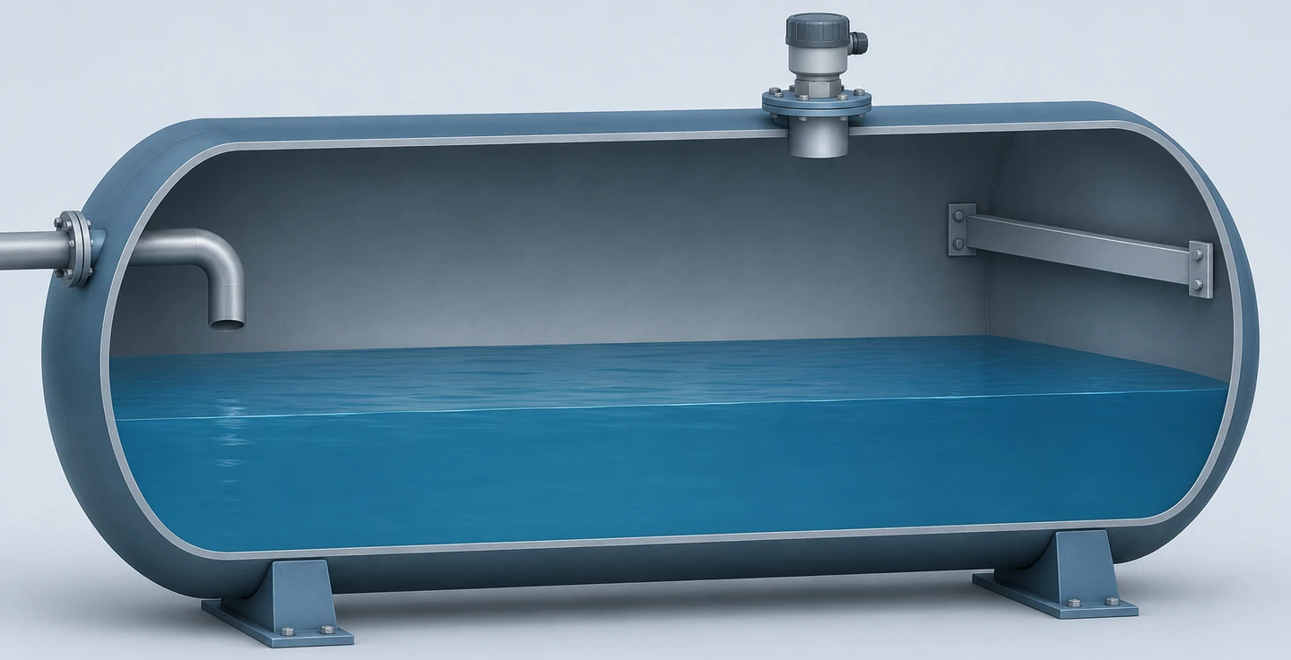
The brace, inlet hardware and wall are possible reflectors. A tank drawing helps relate a return at a fixed distance to a physical feature.
Check the nozzle bore, length and position as well as the transmitter flange size. A deep, narrow nozzle can matter even when the connection threads or flange match. Check the antenna or transducer position relative to the nozzle opening against the installation drawing. Compare the clear path at several distances, because a beam that clears a brace near the top can reach a wall or support farther down. Evaluate dome roofs, curved walls and dished or sloping bottoms with the mounting guidance for the intended device. An off-center location may help in some vessels, but its suitability depends on actual internals and clearances.
A narrower nominal beam can help avoid a known obstruction. Its quoted full angle describes a manufacturer-defined portion of the radiation pattern, and energy can extend outside that nominal cone. Reflections can also reach the receiver indirectly. Use a footprint estimate for drawing review, then use the installation guidance and field evidence for the final decision. The antenna or transducer option and its beam pattern matter more to that drawing check than a frequency label alone.
A return that stays at the same distance while a reference level moves is a useful clue. For example, a fixed reported gap around the elevation of a brace during part of a fill can suggest the transmitter is selecting a structural echo. During filling, a stream may create a temporary competing return which disappears when flow stops. Comparing profiles and timestamps in those states helps distinguish a permanent feature from a transient. Comparing the tank geometry with those observations should precede any change to echo processing.
Many devices offer some form of false-echo suppression. The method and available range vary by instrument. The recorded or filtered profile can affect how the device treats later returns, including a real surface that travels past an obstruction. Echo suppression therefore depends on knowing which return is the product and which is the obstruction, with enough evidence to verify coverage of the affected portion of the normal operating span afterward. Use the manufacturer's procedure and site authorization for any configuration change. Siemens SITRANS LUT400 operating instructions Emerson Rosemount 5408 radar documentation
Work the full distance window before choosing
The closest required distance occurs at the highest surface position in the defined operating range. An ultrasonic transducer generally needs a near interval for transmit ringing to decay and the receiver to recover. Radar models can also have a minimum distance, special near-range processing or a region excluded by configuration. Those terms can describe different behaviors. Confirm the minimum distance for dependable continuous measurement from the actual installed origin, including any impact of the nozzle. The farthest required distance occurs at the lowest operating level and must still provide a usable echo under the expected process conditions.
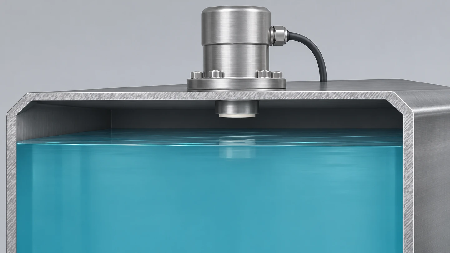
The remaining gap at high level is an installed dimension. Compare it with the documented usable near range and the expected variation in the normal liquid surface.
Worked example for a vented water tank
Assume the device reference is 3.20 m above the tank's liquid-height datum. The process needs continuous indication from 0.40 m to 2.94 m above that datum. These are hypothetical operating levels for a geometry comparison. They do not set a fill limit or define an overfill protection function.
| بررسی کنید | Calculation | نتیجه |
|---|---|---|
| Closest nominal gap | 3.20 m − 2.94 m | 0.26 m |
| Farthest nominal gap | 3.20 m − 0.40 m | 2.80 m |
| Example measured level | 3.20 m − 1.90 m measured gap | 1.30 m |
| Nearest gap with assumed surface variation and installation allowance | 0.26 m − 0.08 m | 0.18 m |
With this assumed nearest requirement, a candidate whose documented usable range starts at 0.20 m would miss it by 0.02 m. A candidate usable from 0.10 m would have 0.08 m remaining in this near-range check. These are illustrative candidate limits. Either candidate would still need review of the far end, including low-level variation, and the particular nozzle and expected echoes. If a retrofit moves the device origin up, it improves top-end clearance and increases the farthest required distance by the same amount. Update the configured datum and repeat the geometry check for that change.
At the 2.80 m gap, the nominal beam radius can be estimated as distance multiplied by the tangent of half the full beam angle. A 4° beam gives 2.80 × tan(2°), about 0.098 m. A 10° beam gives 2.80 × tan(5°), about 0.245 m. A support extending into the path to within 0.18 m of the axis at that distance lies outside the first nominal footprint and inside the second. That comparison identifies a plausible candidate for closer review. The beam boundary is approximate, alignment may shift, and an indirect echo may still be present. Use the same distance to evaluate the structure and the beam at its location.
The near gap can dominate in a shallow day tank even if the longest distance is modest. A deep tank with ample top clearance may instead be limited by the return at low level. For a clean water tank, a well-positioned ultrasonic instrument may fit both constraints. For a tank with the same dimensions and routinely changing solvent vapor or a narrow path around equipment, radar is a stronger candidate for application review. In both cases the drawing defines what the device must measure, and the process tells you how difficult the return will be.
Verify the indication under real operating conditions
Plan the evidence around authorized normal operation and established site procedures. A single quiet comparison at mid-level can confirm the displayed value at that moment. It leaves unanswered whether the device follows the correct echo near the roof, near a brace, during normal inflow or when the headspace has warmed. Identify those conditions in advance and use existing safe observations, accessible diagnostics and an approved reference where available. For hazardous or pressurized vessels, site personnel and the responsible engineering team determine how evidence can be obtained.

Time-aligned level, reference and diagnostic records show how an indication behaves as the process changes.
Put the reference and the transmitter on the same datum and compare timestamps. A reference based on pressure can change with density or headspace pressure. An external gauge may have a different response time or may represent a different physical point. Document which reference was used, its uncertainty or limitations, and whether mixing creates a local difference. Where reference evidence covers only a portion of the span, record that coverage so future operators know which states have been checked.
A useful record ties the displayed level to the sensor distance, echo information or diagnostic status where available, the control-system value and the actual operating state. Compare the local sensor indication with what the controller receives. If local distance tracks the reference and the control screen is wrong by a consistent offset or factor, look at datum or output scaling before attributing the problem to echo physics. If the controller displays a smooth value during an invalid echo condition, determine whether the device, input channel or display is holding the last good value and how quality reaches the operator.
| Observation in routine operation | Possible explanation to investigate | Evidence to compare |
|---|---|---|
| Level drifts as a batch heats | Ultrasonic sound-path error, actual level change or a reference effect | Independent reference, headspace conditions and raw gap |
| Reading sits at one value while liquid moves | Stationary echo selection or stale output | Echo distance, local instrument quality and controller timestamp |
| Dropouts coincide with normal filling | Competing fill stream or reduced return from a disturbed surface | Profiles and quality before, during and after filling |
| Low reading appears as the tank approaches its bottom | Bottom echo or a usable far-range limit | Bottom geometry, validated low-level reference and echo evidence |
| Transmitter agrees but display lags | Device damping, update interval or control-system filtering | Time-aligned device value, input and displayed value |
Set acceptance criteria for the measurement job. Inventory, pump control and batch dosing can have different requirements for bias, response time and the length of a signal interruption. A filter can make a noisy value easier to read while delaying its response. Any assessment of rate and lag should follow the signal from the instrument through the control system at the actual update settings. A trend with believable movement and no obvious jumps still needs reference agreement, quality status and documented operating coverage.
Keep continuous level and overfill protection separate
A continuous transmitter reports a process variable for indication or control. An overfill protection function has a defined detection and response purpose, with requirements for the architecture, dependence on the control system, fault behavior, verification and maintenance. A high threshold in the same display may help operators during normal operation. Its suitability for any claimed protective role depends on the site's hazard assessment and the design and verification of the complete function. Where the site requires an independent protection layer, common dependencies such as a shared sensor, controller or final element must be considered. HSE large-tank high-level safety-system alert HSE vapour recovery overfill bulletin
An installation may use a point sensor or a separate continuous device for the protective function, depending on its requirements. The sensor is one element in a chain that may include logic, an operator response or an automatic final action. An accurate comparison between a process transmitter and a reference is evidence about the process indication. The protection chain has its own verification under the site program. The example distances and checks above concern continuous measurement in normal operation.
Compare the installation as well as the instrument
For a vented reservoir or clean water tank with a clear roof position, first check whether the ultrasonic transducer and controller cover the closest and farthest distances with the required response time. It can be a straightforward fit, especially where the operator already has access to compatible diagnostics and spare hardware. In an outdoor installation, ask how temperature gradients, direct sun on the instrument and condensation at the roof change the assumptions. An instrument installed successfully in an indoor basin may see a different gas path under an exposed tank roof.
For a heated process tank or a crowded vessel, start the review with free-space radar. Ask the supplier to identify the antenna option and the nozzle geometry it can work with, then check the usable distance range for the expected product. A substitute liquid, solvent blend or cleaning cycle can present a different target or change what accumulates on the face. A short-range reading from an open container of clean water provides little evidence about the installed low-level return from a weakly reflective product.
Separate the instrument price from the cost of making the measurement work. A new nozzle, dedicated bracket, suitable process seal, external controller or revised cable run can dominate a retrofit. Include access for inspection under site procedures and the tools staff will use to retrieve diagnostics. Where no candidate provides convincing coverage, the vessel constraints and process data can support a review of different mounting positions or other measurement principles before the control design depends on a signal.
Questions about radar and ultrasonic tank measurement
Can I replace an ultrasonic transmitter with radar in the same opening?
Sometimes. Confirm the new device's measuring origin, nozzle requirements, materials, mechanical and environmental ratings, and applicable approvals. Recheck the near and far gaps and beam clearance against the new antenna. Then verify output scaling, failure indication and controller response. The existing opening is one input to the review and its prior service does not establish a suitable path for the new device.
Can radar measure liquid beneath a foam blanket?
It can in some applications. The quality of the return depends on the foam, the liquid and the instrument. A thin intermittent layer and a thick wet layer may produce different results in the same tank. Confirm which interface the device follows with a suitable reference under the states the process actually experiences.
Why would the indicated tank level rise when the liquid has barely moved?
Check whether the raw gap moved, whether the quality changed and whether the control system still receives fresh measurements. A reduced reported distance can come from selection of a closer reflector or, for ultrasonic, a shift in acoustic velocity. Waves can also raise the actual surface locally. The process timestamp, echo record and reference help separate those causes.
Is a higher-frequency radar automatically better for a crowded tank?
Compare the actual beam pattern, antenna, mounting, documented minimum distance and performance under the expected process conditions. A narrower beam may clear a brace, but the geometry around the nozzle and the echo from the particular liquid remain relevant. A frequency label alone gives too little information for the installation decision.
Is noncontact measurement a good fit for corrosive liquids?
Keeping the instrument above the liquid can reduce direct exposure, but vapor, splash and condensate can still contact the process-facing materials. Check the antenna or transducer, seals and process connection for compatibility with the chemicals and cleaning conditions at the temperatures involved. A suitable measuring principle still needs a suitable mechanical installation.
What should I give a supplier to compare the two technologies?
Provide a section drawing with elevations, the actual nozzle dimensions and locations of the inlet and internals. State the normal liquid height range, relevant product changes, expected foam or deposits, temperature and pressure, and the job of the output in the control system. Ask for the installed usable distance window and the evidence that the selected configuration can follow the liquid in the most difficult routine state.




پاسخ دهید