
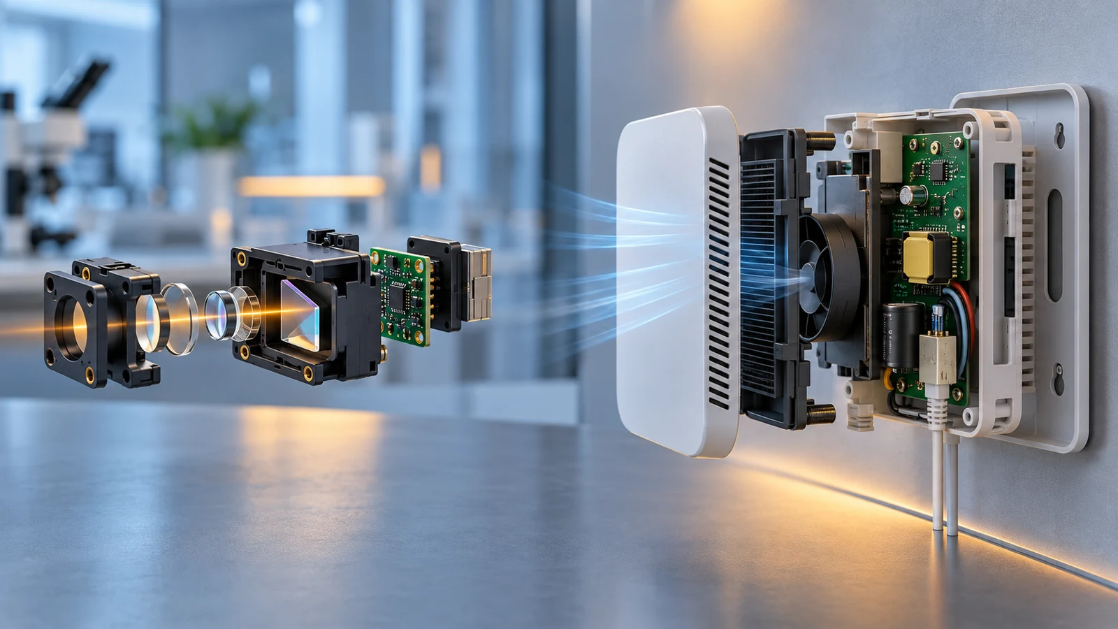
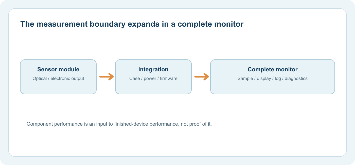
UN CO₂ sensor module is a component that produces a CO₂-related output under stated conditions. A complete CO₂ monitor is an assembled product that admits a sample, powers and interprets the sensor, then presents, logs or uses a reading. The module's accuracy matters, but it does not automatically become the accuracy, response time or intended use of the finished monitor.
This distinction is especially important when a project moves from a development board to a wall unit, duct device, handheld meter or fixed gas detection system. The component and the final device have different boundaries. To compare them responsibly, ask which part has been tested, under what conditions, and what the assembled system must actually do.
Start With the Boundary of the Claim
A module data sheet may specify CO₂ range, error, response, power, interfaces and environmental limits at the sensor or board. The finished monitor adds an enclosure, openings, heat-generating electronics, power supply, display or communication path, software, and possibly alerts or logging. Each addition can change the measurement delivered to a user.
Le US EPA's description of indoor air-quality monitors treats a monitor as a device combining one or more sensors with other components to detect and report selected parameters. It also explains that a monitor reports only what its sensor set is designed to measure. This is a useful boundary: a finished product's advertised capability must be supported by the complete device, not inferred from one component name.
| Question | Module evidence may answer | Complete-monitor evidence must answer |
|---|---|---|
| What quantity is measured? | Sensor target, optical/electronic output, component range | Displayed quantity, units, filtering and validity flags |
| How does gas reach it? | Test fixture and inlet conditions | Enclosure air exchange, location, tubing or flow |
| How accurate is it? | Component claim under data-sheet conditions | Error after assembly and use in the specified environment |
| How quickly does it respond? | Bare-sensor or module test response | End-to-end response including case, sampling and processing |
| What happens when it fails? | Sensor fault/status outputs if provided | User-visible fault, lost power/data behavior and service procedure |
| Can it be used for alarms? | Usually cannot establish whole-system suitability | Documented intended use, alarm behavior and applicable requirements |
The table does not imply that every application needs the same amount of validation. A display for investigating room ventilation and a product used for safety-critical alarming have different consequences and documentation needs. The design question comes first.
How Integration Can Change a Good Sensor's Result
Air Access and Representative Sampling
A bare module may be exposed directly to test gas. Inside a wall-mounted housing, air must enter through slots, cross an internal space and reach the sensing cavity. Placement near a wall, a heat source or a local exhaled plume can change the sample. For a duct monitor, velocity and pressure around the inlet matter. For a remote sample, filters and tubing add transport and maintenance issues.
Sensirion's SCD30 design-in guidelines explicitly address heat sources and airflow-induced pressure effects for that module. Those details are easy to miss if only the headline CO₂ accuracy is copied into the finished monitor specification. The SCD30 datasheet also notes that response time depends on design-in and environment.
Heat, Power and Electronics
The display, radio, processor and supply may heat the enclosure. That can change local temperature and airflow, influencing the sensor and any integrated humidity measurement. The supply must also satisfy the module's electrical requirements during start-up and measurement. A digital interface can avoid some analog noise problems, but software still has to decode status, units and invalid values correctly.
Ask how the finished unit behaves after a power interruption. Does it warm up before reporting valid data? Does it retain calibration settings? Does it show a stale reading as though it were current? These are whole-device questions. A component's ability to produce a serial number does not automatically mean a remote dashboard preserves that identity and the associated calibration record.
Signal Processing and Presentation
An instrument may average, smooth, round or suppress readings. These choices can make a display stable while delaying recognition of a real change. A module's two-second output update, for example, does not mean the room monitor has a two-second end-to-end response. For analysis or control, the reported value needs a timestamp, units, a clear averaging rule and status information.
There is also a difference between a direct CO₂ channel and an estimated eCO₂ value derived from another pollutant sensor. A polished case does not make the latter a direct measurement. Our direct CO₂ versus eCO₂ explanation covers this distinction.
Accuracy Claims Need Their Test Boundary
Consider a hypothetical monitor assembled around a module whose data sheet states ±(30 ppm + 3% of measured value) within its specified interval. It would be inaccurate to advertise that formula as an independently verified finished-monitor accuracy without checking the effects of the case, power, sampling position, temperature and firmware. The module's number remains useful as a component selection criterion. It is not proof of the assembled outcome.
The same boundary applies to range. A module's interface may report numbers well beyond its accuracy interval. Our range selection guide explains how to compare the application decision band with the specified accuracy band. At the device level, also check what the user sees when the sensor is overrange or reports a fault.
If a manufacturer provides a complete-monitor accuracy specification, inspect the conditions: calibration method, temperature and humidity range, pressure, sampling arrangement and whether the number includes the display or communications output. If these are absent, ask for clarification rather than assuming the claim is universal.
Module, Probe, Transmitter and Monitor Are Practical Roles
Product names vary. A “sensor” can mean a chip, optical engine or packaged module; a “probe” may be a calibrated assembly; a “transmitter” may output a concentration signal to a control system; a “monitor” may provide a local display and logging. The names alone do not settle the system boundary. Read the model's supplied hardware and documentation.
Vaisala's GMP343 CO₂ probe documentation illustrates why this matters: it offers different diffusion and flow-through configurations with response information for each. It is more complete than an unintegrated optical element, yet a probe installed within a larger control or logging system still depends on that system's sample routing and data handling. The comparison is about boundaries, not a ranking of product names.
A room monitor might contain a probe or module, a display and a radio. A gas analyzer might contain similar optical technology with a pump, flow control and more explicit sample conditioning. The measurement task and the gas sampling route separate those roles more clearly than the product label does.
A Four-Layer Review for a Finished CO2 Monitor
Layer 1 — the sensing component. Verify target gas, method, range, accuracy interval, environmental limits, response definition, calibration behavior and diagnostic outputs for the exact part number.
Layer 2 — sampling and installation. Trace how air reaches the sensor in the assembled product. Check enclosure openings, potential condensation, local heat, pressure difference, mounting location and expected airflow. For a pump or tubing, specify flow and transport delay.
Layer 3 — processing and interface. Confirm firmware version, filtering, units, fault handling, communication timeout, data timestamps and which values are stored. Separate live displayed values from logged averages.
Layer 4 — intended use and maintenance. Identify whether the device is for indicative room trends, process control, investigation or alarm duty. Obtain the complete product's operating and service instructions, calibration procedure and any needed evidence for the application.
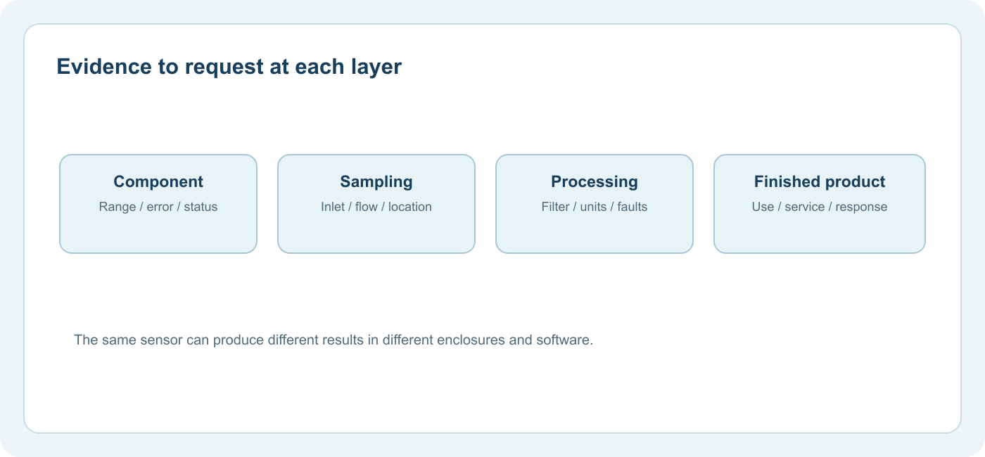
This framework helps avoid both extremes: dismissing a sound component because the finished device is poorly described, and treating a reputable component name as proof that every enclosure and firmware implementation is sound.
How to Check an Integrated Prototype
For a prototype monitor, compare the device with a suitable reference under defined conditions rather than relying on the module data sheet as the acceptance result. Record where both instruments sample, their time bases, stabilization periods and the conditions being compared. Inspect the air path through the assembled enclosure. Review a step change to see whether the displayed response includes unexpected delay or smoothing, and verify that an invalid sensor status does not appear as a plausible concentration. These checks do not create a universal accuracy certificate; they expose integration issues that a bare module test cannot see.
Next, repeat the comparison after the device reaches normal operating temperature and after representative power states, such as a radio transmission or a display backlight change. If the final product has a closed housing, the reference should be arranged so that both readings describe comparable gas, rather than placing one sensor in a different microenvironment. Keep firmware revision and calibration settings with the record. When the prototype changes, evaluate whether the evidence still applies to the changed enclosure or processing. The practical aim is to establish what the finished product actually reports.
What to Ask a Supplier or Integrator
The most efficient request is a small evidence package. Ask for the exact module and finished-device model identifiers; the current data sheets and manual; accuracy and response conditions for the complete product; the sampling diagram; calibration instructions; and a description of fault and overrange behavior. If alarms are involved, ask for the intended-use documentation for the whole device, including installation and maintenance requirements. Avoid substituting an unrelated component certificate for finished-device evidence.
For an OEM project, also ask who owns the integration work: enclosure design, firmware interpretation, field service and changes to the bill of materials. A module may be factory calibrated, yet replacement of a module in the field can require identity management or a check of the finished unit. Record the serial number and revision where the application demands traceability.
Le CO₂ measurement guide frames these questions along the full sample-to-output path. Gasnose's NDIR sensor guide is a useful companion for evaluating optical technology before it is placed in a product.
Examples of Claims and Their Real Scope
| Statement | What it may reasonably support | What it does not prove alone |
|---|---|---|
| “Uses an NDIR CO₂ module” | The identified sensing principle | Final-device accuracy or alarm suitability |
| “Module measures every two seconds” | Component update capability under its interface conditions | Two-second response at the finished display |
| “Factory calibrated sensor” | Component calibration at its specified conditions | Correct sampling, installation or field behavior |
| “Display shows 0–40,000 ppm” | The output can represent that span | Accuracy throughout the span |
| “Wireless data available” | A communications feature exists | Timestamp integrity, no lost data or correct fault reporting |
These distinctions should appear in the product documentation itself. The comparison need not be adversarial: a clear module specification is an excellent foundation for a well-engineered monitor. It simply is not the whole product.
Questions fréquemment posées
Is a calibrated sensor module enough to build an accurate CO₂ monitor? It is a strong starting point. The finished device still needs suitable sampling, electrical integration, processing and validation under its intended conditions.
Does a sensor module include an alarm? Usually a module supplies a measurement or status output. A finished alarm system adds logic, annunciation, power behavior, installation and documented intended use; check the exact product.
Why can a finished monitor respond slower than its sensor? Gas exchange through the housing, tubing, filters and firmware averaging can add delay beyond the module's own response test.
Can two monitors with the same module behave differently? Yes. Enclosure, firmware, placement, calibration settings and maintenance can differ. Compare the finished-device specifications and test boundaries.
What is the first document to request? The complete device's current manual and data sheet, followed by the component data sheet if the sensing architecture matters to the decision.
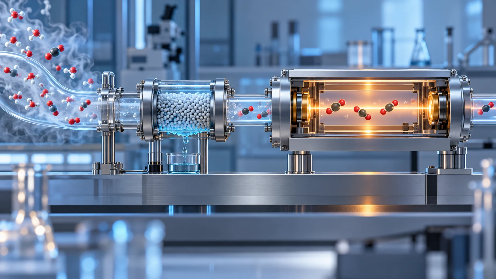
Lectures de CO2 humide ou sec : pourquoi la base d'échantillonnage modifie le nombre
Les ppm de CO2 dans l'air humide et dans l'air sec peuvent différer car la vapeur d'eau modifie le dénominateur de la fraction. Apprenez la conversion conditionnelle et ce qu'il faut enregistrer dans un système de gaz échantillonné.
En savoir plus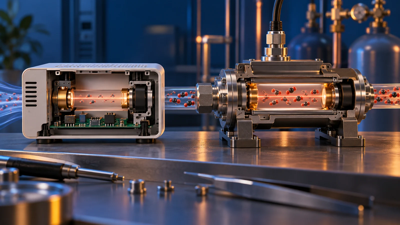
Plage du capteur de CO2 : choix de la mesure en ppm ou en pourcentage
Choisissez une plage de mesure du CO2 autour des concentrations et des décisions qui comptent. Comparez les unités ppm et pourcentage, les intervalles de précision, le comportement hors plage et les conditions d'échantillonnage.
En savoir plus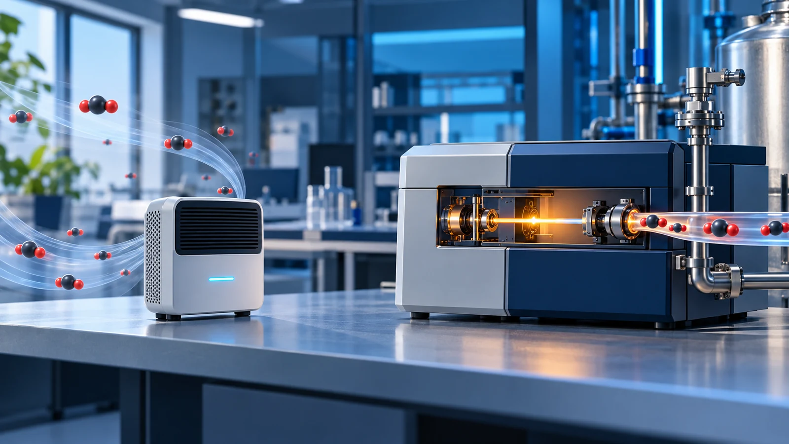
Moniteur de CO2 vs analyseur de gaz : échantillonnage, données et choix d'instruments
Comparez les moniteurs de CO2 et les analyseurs de gaz par point d'échantillonnage, trajet du gaz, plage de mesure, résolution temporelle, preuves d'étalonnage et décision prise en charge par les données.
En savoir plus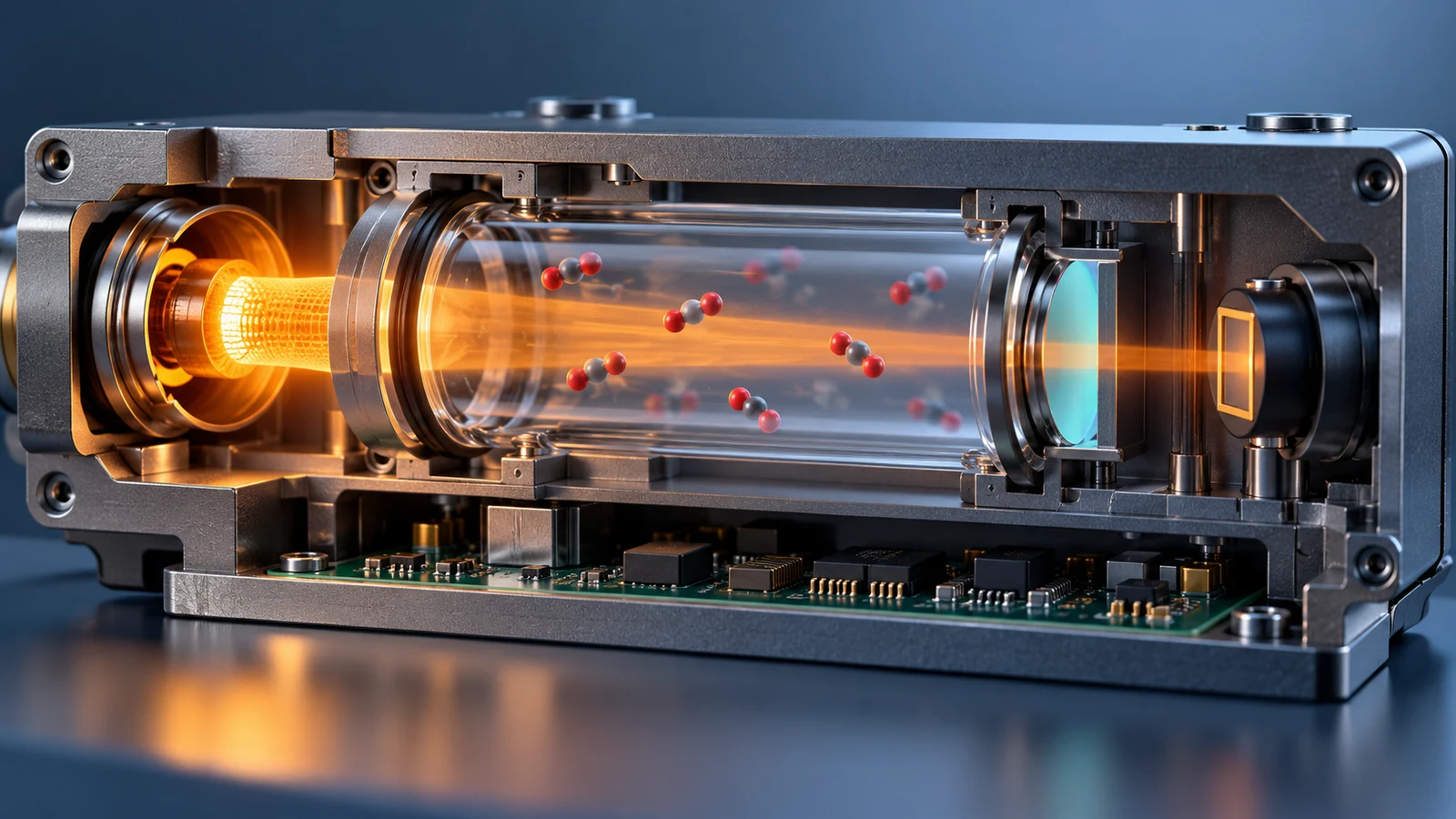
Capteurs de CO2 NDIR : comment fonctionne la chaîne de mesure
Suivez la chaîne de mesure du CO2 NDIR depuis la source infrarouge et la cellule à gaz jusqu'au filtre, au détecteur, au signal de référence, à la compensation et à la sortie calibrée.
En savoir plus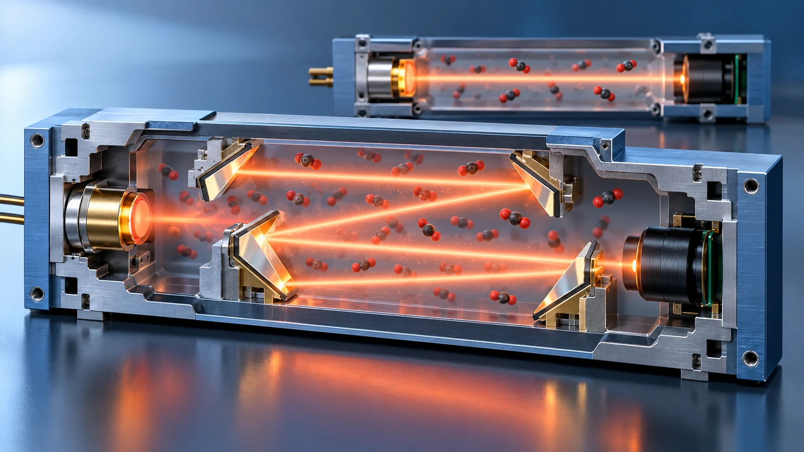
Longueur du chemin optique dans les capteurs de CO2 : plage, sensibilité et taille
Découvrez comment la longueur du trajet optique NDIR affecte le signal à faible teneur en CO2, la plage de concentration élevée, la géométrie des cellules et la taille du module, ainsi que les spécifications à comparer.
En savoir plus
Canaux de référence NDIR : ce qu'ils corrigent et ce qu'ils ne peuvent pas
Comprendre la référence optique dans les capteurs de CO2 NDIR : dérive en mode commun, contamination par chemin partagé, limites de température et de pression et implications en matière d'étalonnage.
En savoir plus
Commentaire (1)
[…] sample-to-output chain. For the distinction between module claims and finished equipment, read CO₂ sensor modules versus complete monitors. To compare different sampling and data tasks, read CO₂ monitors versus gas […]