
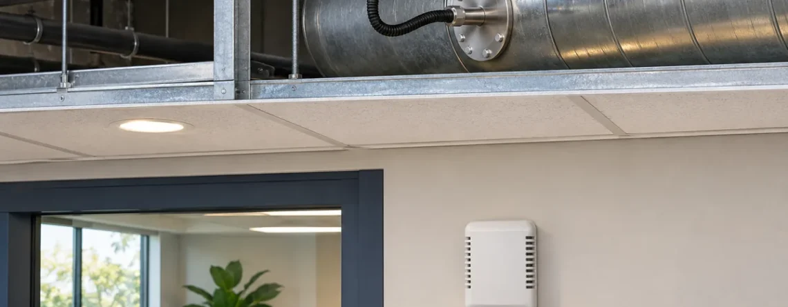
Choose a room CO₂ sensor when the decision concerns the air in a particular occupied space. Choose a duct transmitter when the decision concerns a defined air stream. A dedicated return branch may serve as a proxy for one occupied zone when the return actually represents that zone, the operating range has been checked, and the governing requirements allow it. A shared return measures a combined stream and can conceal the room with the highest concentration.
A good selection starts with a question rather than an enclosure type. Will the reading reset the airflow to a specific room, support a central diagnostic, or characterize outdoor air entering the system? Locate the point where that air is actually available. Then select the transmitter, installation and validation method that can measure it under the relevant modes.
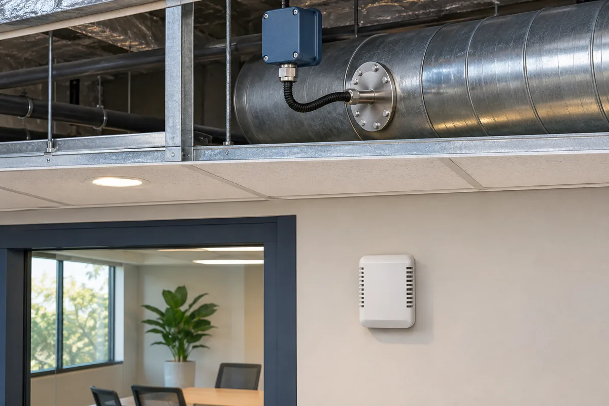
The two instruments can both work correctly while reporting different air samples. The control decision determines which sample is useful.
Name the physical sample and the decision it supports
An occupied room is a physical space. A thermal control zone is the space or group of spaces served by a common control action. A return branch is an air path. These boundaries can align, but many installations combine multiple rooms under one terminal or share a return path through a ceiling plenum. A point called “zone CO₂” in a control system could come from any of these locations unless the drawings and point list identify the actual inlet.
A room transmitter samples air near its enclosure, typically through openings exposed to room air. A duct transmitter has a probe or sampling arrangement designed for installation in a moving air stream. The equipment designation says how the instrument is installed, while the duct arrangement says which air reaches it. A “return CO₂” point upstream of outdoor-air mixing may describe return air. The same probe installed downstream of the outdoor-air mixing section measures mixed air. Its reading cannot be interpreted as a return reading merely because the control system labels it that way.
| Measurement objective | Suitable starting point | Apa yang harus diverifikasi |
|---|---|---|
| Occupied room condition or local ventilation request | Representative room point, or several if required | Occupant distribution, air jets, doors, applicable location requirements |
| Dedicated return as a permitted zone proxy | Return stream serving the zone before other branches join | Exclusivity, leakage, bypass, airflow, room agreement over modes |
| Aggregate air-handler return trend | Verified common-return sampling point | Mixing across the duct section, contributing branches and flow state |
| Outdoor background for a control sequence | Representative outdoor intake sample | Suitability for outdoor service, intake source and contamination |
| Mixed-air or supply concentration for a defined diagnostic | Duct point downstream of the relevant mixing section | Adequate mixing, correct location and interpretation of the stream |
Itu ASHRAE Handbook chapter on design and application of controls identifies a particular weakness of a multizone return or plenum reading. It represents a combined concentration and gives little information about rooms with the highest concentrations. This matters most where different populations and airflow schedules share the same return system.
Understand the arithmetic of a common return
If several incoming branches are fully mixed at the sampling point and have comparable density, the mixed concentration is approximately the sum of each branch concentration times its flow, divided by total flow. A small high-CO₂ branch can have little effect on the common value when a large low-CO₂ branch dominates the airflow.
Suppose a packed meeting room returns 120 L/s at 1,400 ppm. A lightly occupied open area returns 480 L/s at 650 ppm. The ideal mixed concentration is (120 × 1,400 + 480 × 650) / 600 = 800 ppm. The meeting room is 600 ppm higher than the common reading. A technician seeing only 800 ppm cannot recover the individual room concentrations, since many combinations yield the same mixture.
If the branch flows become 60 L/s and 540 L/s with the same local concentrations for a constructed snapshot, the ideal return is 725 ppm. The common reading falls even though the occupied room concentration in the example is unchanged. This is an arithmetic comparison at fixed assumed concentrations. In an actual room, a change in airflow can change concentrations over time as well as weights at the return.
| Kasus | Meeting room return | Open area return | Ideal mixed return |
|---|---|---|---|
| First operating state | 120 L/s at 1,400 ppm | 480 L/s at 650 ppm | 800ppm |
| Lower meeting room return contribution | 60 L/s at 1,400 ppm | 540 L/s at 650 ppm | 725 ppm |
| Equal flow contributions | 300 L/s at 1,400 ppm | 300 L/s at 650 ppm | 1,025 ppm |
Real return systems may not mix completely at a single point. A probe near a tee may sit in a stream from one branch. A leak in a negative-pressure return duct can add ceiling-plenum air. A nearby supply leak can dilute a return plenum. An apparently accurate common-return reading may therefore be lower or higher than the calculated bulk average, depending on the local stream and mode. Establish what the point can represent before using it to drive an important action.

Separate rooms can contribute different concentrations and airflows to a common return. The illustration shows the room context without prescribing duct routing.
Clarify the role of a common return sensor
A common return can provide useful system-level context. A normal range under comparable schedules can help identify a broad change, or support analysis of a properly defined air-handler mass balance. If the design uses local sensors to regulate individual terminal requests, a central reading can be an additional diagnostic channel. It cannot independently establish that each occupied room meets its ventilation requirement.
Suppose a return point is stable while staff report a recurring high concentration in one room. The system trend and the room report can both be correct. Inspect the room's branch, occupancy, supply and return path, and compare synchronized local readings. Increasing outdoor air to an entire air handler may change the mixed trend while leaving a specific delivery fault unresolved.
When a dedicated return can work
A single occupied room with a dedicated return can sometimes produce a reliable return proxy. This depends on air reaching the return after passing through the occupied space, a sufficiently representative room-to-return relationship, adequate flow at the sampling point, and permission under the applicable project criteria. A room with more than one return path requires a check of which branch the probe sees. A branch exclusively associated with a room can still sample a region that does not represent the typical occupied air.
Return and room values may differ by operating mode. With ceiling supply and ceiling return, supply air can reach the return along a short path before mixing through the occupied zone. In a stratified space, a high return can deliberately extract warmer air with a different concentration from the air at occupied height. A lightly occupied room may show acceptable agreement during one test simply because all points are near incoming background. The stronger comparison includes a meaningful occupied rise and more than one relevant fan state.
Berkeley Lab's DCV monitoring study compared return-grille and occupied-room measurements during selected meetings. The results varied by room. This supports testing the relationship in a specific installation instead of assuming that every wall sensor or every return grille is intrinsically representative. The Siemens DCV application guide also notes how return plenums and leakage can affect the sample. Its older standard references should be read in their edition context.
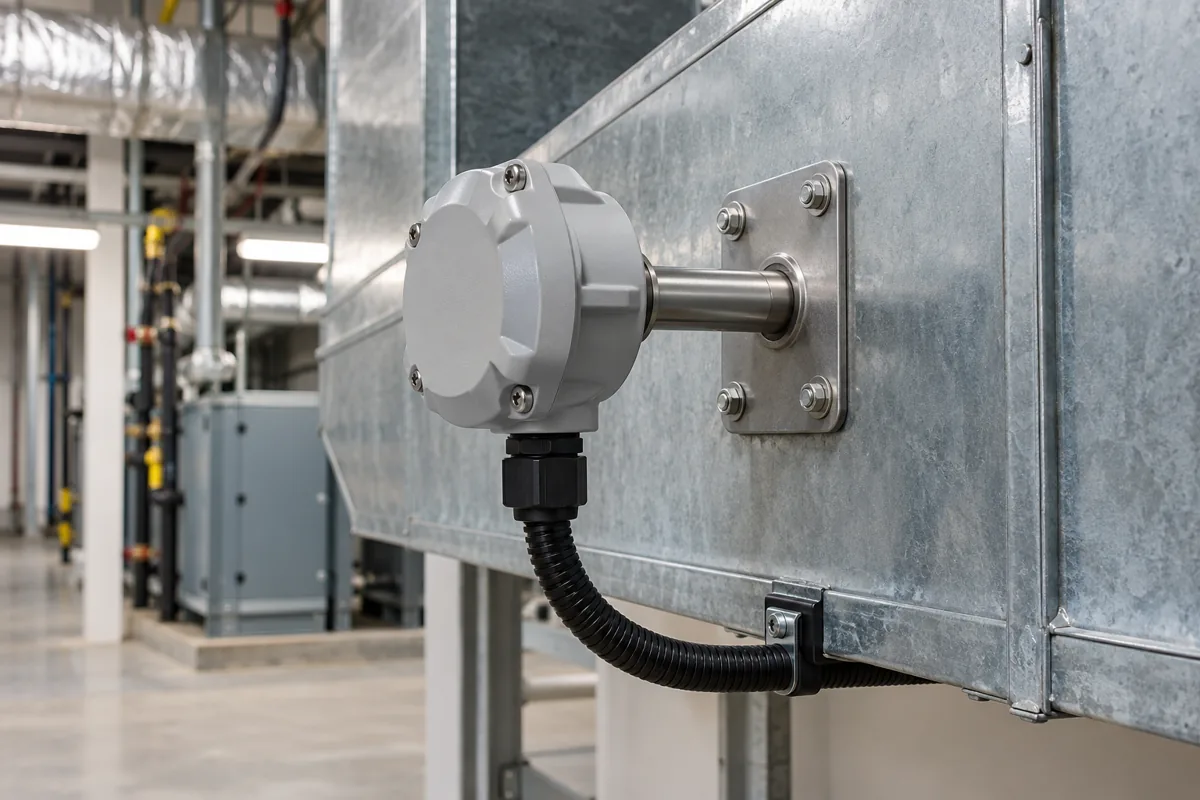
Duct access is useful for service. Confirm the actual air stream, probe insertion and manufacturer mounting requirements before installation.
Choose the hardware after confirming the sample path
For a duct transmitter, review the manual for mounting orientation, insertion depth, probe and enclosure arrangement, duct pressure and velocity limits where stated, and service access. Some assemblies draw air through tubes by pressure differential, while other models place a sensing tip in the duct. These designs can have different airflow requirements. Confirm the model-specific instructions rather than applying a generic probe specification.
Check that the proposed location is reasonably representative across its cross-section. Avoid assuming a point immediately after a branch connection, damper or poorly mixed section describes the whole stream. Use the location guidance for the actual sensor, and obtain a suitable comparison or traverse when the application requires bulk concentration. Confirm how the installation behaves at minimum flow, not only at design fan speed. A duct point with little or no airflow can report stagnant air near the probe.
Mount and seal the assembly according to the product instructions. Evaluate exposure to condensation, washdown, moisture sources, temperature extremes and contamination. Keep the sensing head accessible for comparison or replacement. The Vaisala GMD110 duct transmitter guide is an example of a model-specific manual covering mounting, wiring, output and maintenance. Its requirements apply to the identified instrument.
The GMD110's mounting overview, for example, specifies a minimum duct diameter of 160 mm for that model, with the probe installed perpendicular to the duct wall and the sensing element as close to the duct center as possible. It also advises avoiding dead legs. That geometry is a device-specific installation constraint. It does not guarantee a fully mixed sample in an arbitrary duct. Check the available cross-section and the actual flow pattern as separate requirements.
For a room transmitter, select a point near the occupied region with open air access to the inlet. Keep it away from a supply jet, exterior openings, nearby exhalation, enclosures and furniture that blocks exchange. Evaluate how people use the room, including the positions of chairs, partitions and frequently opened doors. A wall location that was reasonable before remodeling may become unrepresentative when a workstation or return path moves.
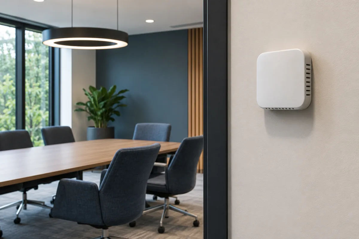
Allow room air to reach the enclosure freely, and review nearby furniture, openings and occupied positions.
Itu Vaisala GMW80 series location instructions give a concrete example of an overlooked wall installation detail. They call for sealing the cable opening because air behind the wall can enter the transmitter and alter the sample. Treat that instruction as specific to the enclosure and installation method. Check the selected unit's location and mounting instructions directly.
Itu Panduan akurasi monitor CO₂ explains how to compare stated tolerance terms at the concentrations that will affect a decision. Read the full transmitter specification and installation conditions as part of the selection.
For both styles, confirm CO₂ measurement range, applicable accuracy, environmental limits, filtering, data freshness and maintenance. Some displays show CO₂ estimated from another measured compound. Such an output follows a different signal and may be unsuitable for an application that calls for direct CO₂ measurement. If automatic baseline correction is offered, check its assumptions against the operating schedule and air exposure before relying on it. A continuously occupied space or a recirculating return may never see the assumed low baseline.
Connect the sample to the correct building point
In an analog installation, a controller's configured range needs to match the transmitter output range. A sensor configured for 0–2,000 ppm can be interpreted incorrectly if the input scale expects 0–5,000 ppm. Validate multiple points through the complete signal chain. On a digital network, verify register mapping, scaling, quality flags, units and update behavior. Record whether the operator screen shows the direct value or a processed point.
Point labels should retain the sample identity. For example, “Training room occupied CO₂” and “AHU-2 common return CO₂” describe different quantities, even if the same transmitter family is used. Add the physical sensor location and served area to the point list. This avoids errors when replacing a probe, comparing trends or changing a sequence.
Validate the proposed proxy with paired room and duct observations
Begin with a plan of the actual airflow paths. Trace supply and return from the room to the air handler, including any shared plenum, transfer opening, bypass or exhaust that changes the balance. Check drawings against visible installation and current operating conditions. Identify the controlled space and review which sensors are intended to affect it. If the governing requirements call for an occupied-room sensor, agreement with a return does not by itself authorize substitution.
Next, compare the instruments in the same stable air or use a suitable reference to understand instrument disagreement. Record timestamps, averaging and response settings. A duct probe with a sample line and a wall monitor with internal filtering can show different timing even when both see similar air. If a fixed sensor cannot be moved for collocation, use a portable comparison at a suitable same-air access point rather than treating a comparison across different streams as a calibration test.
Place one or more reference loggers in representative occupied locations. Where the air distribution is uneven, record the range across points instead of choosing the value closest to the return. Keep the room observations synchronized with the duct point and retain occupancy, mode, fan speed and terminal airflow. A return point should be evaluated when the room is occupied and its concentration changes, not only when the room is empty.
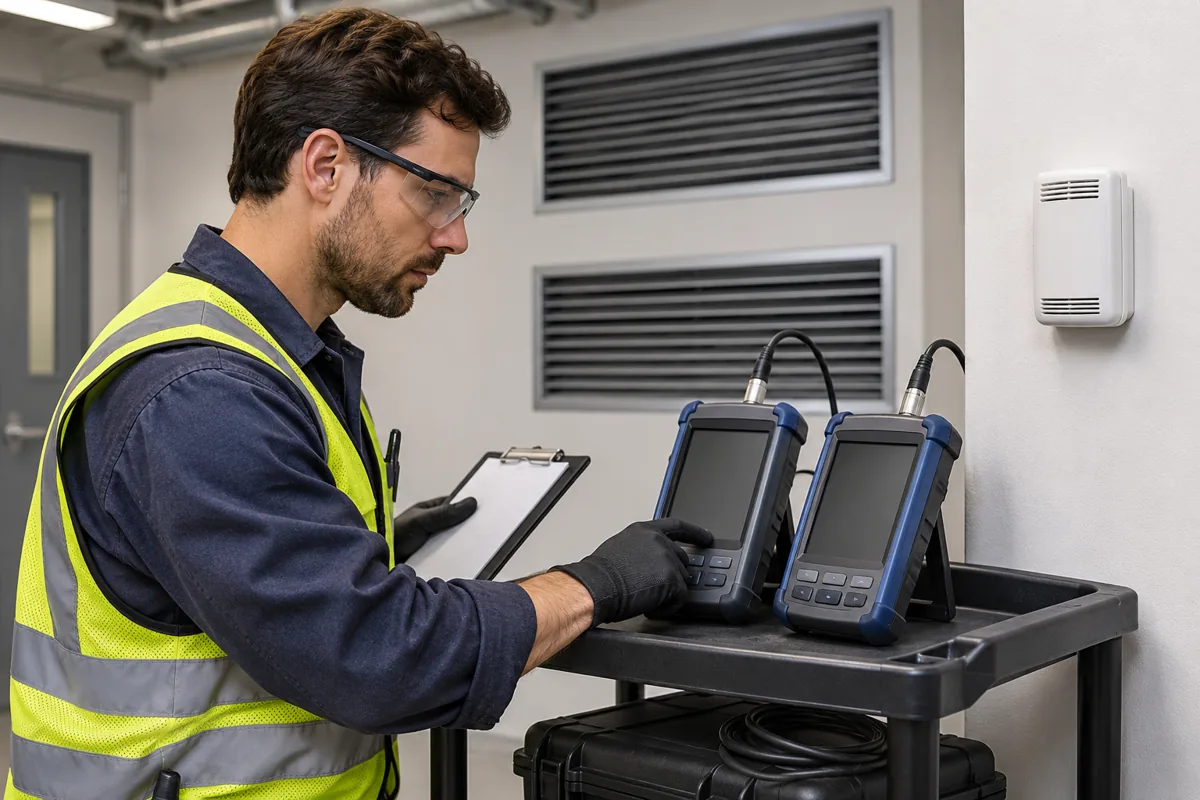
Compare synchronized traces after checking instrument agreement. Record fan and terminal mode alongside each comparison.
Examine direction, size and timing of disagreement
Suppose the occupied reference rises to 1,200 ppm during a full session, while the dedicated return peaks at 1,160 ppm several minutes later. That might be useful agreement for a particular diagnostic, provided the difference and delay are acceptable under the project criteria. If the same return remains near 750 ppm during a low fan-speed session with similar occupied readings, the test suggests the proxy depends on operating mode. A suitable acceptance decision needs both results.
A steady offset can reflect instrument disagreement or a persistent difference in sample air. A difference that changes with fan speed may indicate duct leakage, a change in mixing or sample flow. A delay that follows sample tubing or configured filtering can be different from transport lag between room and return. Evaluate each possibility with an appropriate cross-check. Avoid applying a numeric offset correction until the reason for the difference is known and repeatability has been established.
| Paired trend pattern | Interpretasi yang masuk akal | Follow-up check |
|---|---|---|
| Stable discrepancy after room and return equilibrate | Sensor offset or consistently different air at the two locations | Same-air comparison and review of airflow paths |
| Agreement at high flow, divergence at minimum flow | Changes in duct sampling, leakage, bypass or room distribution | Probe conditions and additional room observations at minimum flow |
| Return remains low while one room rises | Common-return dilution, short-circuit or a different branch than expected | Confirm topology and branch flows, then compare local samples |
| Return freezes when fan stops | Stagnant sample, stale point or filtering | Fan proof, update status and sequence invalidation rules |
| Return changes later than room across modes | Transport, tubing purge, internal response or logging differences | Compare time alignment and matched response in a controlled change |
Include normal occupied startup, high and minimum supply flow, applicable heating and cooling modes, economizer operation where relevant, and fan-off conditions. Define acceptable performance against the required control response, allowed difference and time delay. A system used only for a diagnostic trend can tolerate different limitations from an input that immediately reduces ventilation. A required zone sensor still needs its own verification regardless of the quality of the common return signal.
Apply the choice to three common configurations
In a small, dedicated single-room unit, the wall point is the clearest starting choice when room concentration drives the response. If access or damage concerns favor a dedicated return, first confirm that the return reliably tracks the room and is permitted. Observe a typical occupied event and a low-flow condition. If one mode changes the relationship materially, the duct probe may remain useful for diagnosis while the room retains its control point.
In an air handler serving several independently occupied rooms, use local inputs for local control decisions where the project calls for them. One shared return value averages the air it receives. A low-flow or densely occupied room can disappear from that average. The air handler still needs a valid central flow or system calculation to respond to zone requests. Room sensors and central outdoor-air measurements are complementary.
In a large room with displacement or other stratified distribution, start by deciding which heights describe the occupied condition. A return may intentionally represent a layer above occupants. Even if one average is useful for energy or return diagnostics, a local point can answer a different question about the people zone. Compare representative locations and conditions before using a single point for automatic control.
Specify what happens when the sample path changes
A duct installation is sometimes selected for service access, but access and sample validity can change independently. A balancing contractor may adjust branch flows, or a renovation may introduce a shared return through a plenum. The sensor remains in the same place while the contributing air changes. Include the sample path and served spaces in the record so a future technician can see why the point was considered suitable.
A room installation can also change without any equipment replacement. A divider can create a distinct occupied region. A new desk can place exhaled breath next to a wall transmitter. A supply grille adjustment can move the discharge onto the inlet. Review actual room use after changes that alter occupant location, air paths or nearby sources. A trend that starts to differ after construction can reveal a location change rather than instrument drift.
For a candidate dedicated return, write an explicit decision statement before testing. It can name the measured branch, the occupied reference, the modes assessed, the period of observation and the criteria for agreement. If all evidence covers high-flow cooling, leave other modes unevaluated until data are available. A shared return measurement used only for system trending should be labeled accordingly. Clear documentation prevents a diagnostic point from being reused for a stronger control claim without review.
Check uncertainty at the points where decisions change
The control action may switch or start to ramp near a setpoint. A difference that appears minor across a full day's range can matter if it places one point on each side of that boundary. Compare room and return agreement specifically around the range of concentration at which the control makes decisions. Include repeat events and the timing of crossing. The test can reveal that two points have similar averages and different useful response times.
A supervisor may want to assign one offset to align return and room trends. Consider whether the difference is stable across operating mode and measured range. An offset derived from one occupied period is weak evidence when branch mix varies. For example, the constructed mixed-return calculation above changes by 75 ppm solely from changed flow weights. No fixed correction to that one central point can reconstruct unknown room values across independent conditions.
Preserve a simple record for operations
The handover can list every point with a device ID, location, physical sample, controlling sequence and appropriate use. Record maintenance access and comparison method. Identify whether the point loses representativeness during fan-off and how long it takes to regain representative sampling. If both room and duct points are available, retain them separately in operator trends and show fan state with each comparison.
For a building upgrade, first investigate any mismatch at the location where it appears. A room concentration that increases while the dedicated duct reading remains unchanged can motivate a check of airflow path, occupied location or data validity. If another room starts influencing the duct point after a return modification, rename or reclassify the point. Use the original acceptance record to see which assumptions no longer apply.
Pertanyaan yang sering diajukan
Can one duct sensor replace several room sensors?
A common return typically represents an aggregate stream. It can miss a high concentration in a lightly weighted branch. For independent zone decisions, use the measurement arrangement required by the design and governing requirements. A dedicated return can be considered for the zone it exclusively serves where validated and allowed.
Is the duct sensor inherently more accurate?
Check accuracy for the specific models and installation conditions. Duct mounting and wall mounting expose the sensing element to different air and environments. A device can meet its concentration accuracy while reporting the wrong air stream for the decision.
Should a duct probe go in the return or supply?
Place it in the stream the diagnostic or control method calls for. Return, mixed and supply air can have different concentrations because outdoor air and recirculated air combine in specific locations. Label the actual sample point and review mixing before interpreting the value.
How should the controller use the duct reading with the fan off?
Verify whether the design requires valid sample flow and how fan proof or data validity is represented. With the fan off, the air around the probe may not represent the served area. Follow the approved invalid-data handling and document the recovery once representative flow resumes.
What if only one room sensor is affordable?
Place the available sensor where its result supports the most important defined decision and recognize what remains unobserved. A portable survey can help determine whether the occupied region is sufficiently uniform or whether additional locations are necessary. Do not use a shared return to assume away a known room-level requirement.








Tinggalkan Balasan