
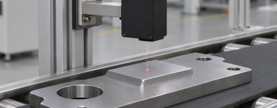
Choose a laser triangulation displacement sensor around the distance and surface it must measure in the machine. Establish the part datum, work out the nearest and farthest possible target positions, and check that both the laser beam and the return to the receiver stay clear. Then make sure the spot fits the smallest feature at those positions and that the controller receives enough valid samples while that feature passes. Confirm the assembled measurement against an independent reference using production parts at the intended speed.
A sensor that repeats to a few micrometers on a stationary calibration target can still miss a narrow step, follow a glossy reflection, or report motion of its own mounting bracket. A useful evaluation separates optical return, measurement geometry and controller timing so that each failure can be detected on the bench or the line.
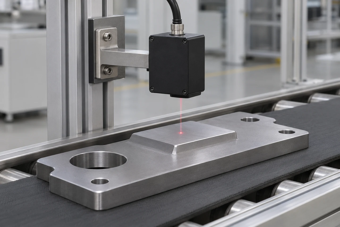
An overhead head observes one area of the passing part. The chosen datum and the controller's selection of samples determine what dimension the station reports.
Define the measurement and the datum
A point triangulation head projects a spot on the target. A receiver lens, offset from the emitter, forms an image of returned light on a position-sensitive detector. A change in target distance moves that image on the detector. The head or its controller maps the detected image position to distance using its calibrated optical geometry. The return has to reach the receiver with a shape and intensity the sensor can interpret. The manufacturer's explanation shows how detector position, optical angle and usable span relate. Vitrek laser triangulation principles
Distinguish the head's distance reading from the dimension the machine needs. For an overhead head with a vertical beam, the top moving up makes the gap smaller. If the control screen defines upward displacement as positive, compute reference gap minus current gap. For height above a fixed machine datum, the reference gap is the gap to that datum in the same geometry. For a step, compute the gap to the lower terrace minus the gap to the upper terrace. Where the sensor is tilted relative to the dimension of interest, the beam intersects a different point as distance changes. Establish the conversion and spot location with the actual fixture and part, especially on a sloped face.
| Measurement task | What must be held or measured | What one point head can confuse with the result |
|---|---|---|
| Travel of a stop or actuator | A stable sensor frame, defined measurement axis and a reference position | Bracket flex, target rotation or movement of the spot across a slope |
| Top height above a fixture | Known gap to a fixed and repeatable support datum | Part lift, seating debris or wear in the support |
| Step height on a passing part | Two valid readings on the appropriate terraces, or a shared profile with an in-part reference | Fixture movement between reads, edge returns, or samples assigned to the wrong terrace |
| Thickness of a free-moving sheet | Both faces at matching positions and times, and a calibrated separation between measurement origins | Vertical sheet motion if only the top face is observed |
For opposing heads on a common axis, with gaps measured inward from a known separation, thickness = separation − upper gap − lower gap. The simple subtraction assumes stable relative mounting and aligned readings. For example, vertical sheet motion at 40 mm/s with 0.5 ms of timing skew can contribute roughly 0.020 mm of error at that moment. Spot misalignment on a sloped or rippled sheet adds a separate error because the two heads interrogate different positions. Where the bottom face seats against a proven reference, a single head can measure thickness relative to that support.
If a moving part can pitch or lift while one head reads its two terraces, an aligned pair or a 2D laser line profiler can capture both heights together. A profiler also helps when a narrow feature can drift sideways out of the point head's path. A single spot works well where the measurement track and datum are fixed or can be identified repeatably. Time-of-flight distance sensing uses a different ranging principle and has its own spot, range and timing specifications. KEYENCE step-height measurement guide Sensor1stop optical sensors overview
Match the installed distance window
A range specification needs two endpoints. A head rated for a 10 mm measuring span could work from 20 to 30 mm, with a 25 mm reference distance. The 10 mm span describes how far the target can move within the measurement interval. The 25 mm reference tells you where the head and part sit relative to each other. Find the drawing's distance origin on the head and note which mounting mode the drawing describes. For a head with diffuse and specular mounting configurations, read the drawing and limits for the intended configuration.
Make a distance budget in a common sign convention. Include part height tolerance, position or runout, fixture repeatability, bracket adjustment, and any drift that can move the head relative to the part. Use realistic combinations of extremes. At a nominal 60 mm gap, suppose part and process variation can shift distance by up to 3.0 mm either way, and fixture and mounting variation add up to another 1.5 mm each way. The required interval is 55.5 to 64.5 mm before adding any design margin. A catalog interval of 55 to 65 mm would leave only 0.5 mm at each end. That margin might disappear after a fixture change or with a new part variant. The holder must also provide physical clearance for part transfers and abnormal motion.
Check usable optical performance within the distance window, not just whether the reading stays within range. For one example, the Micro-Epsilon ILD1320-10 lists 20, 25 and 30 mm as start, midpoint and end. Its listed spot dimensions at those points are 100 × 130, 45 × 50 and 158 × 200 µm. The largest nominal spot dimension at the far end is four times the largest at the midpoint. The catalog specifies a ±10% tolerance on the spot dimensions. A feature that measures cleanly on a centered bench part may therefore need more edge clearance at the farthest production gap. Use the spot table for the actual head and the positions your process occupies. Micro-Epsilon optoNCDT catalog
| Data-sheet term | What to establish before comparing models |
|---|---|
| Repetabilitate | Target, stand-off, measurement rate, averaging, and whether the statistic is a standard deviation, spread or another reported quantity |
| Rezoluţie | Smallest reported or discernible change under stated conditions and whether the number is limited by noise, digitization or the output interface |
| Linearity | Reference curve or line, valid interval, units, and whether the number is typical or a limit |
| Temperature stability | Reference temperature, units per degree and whether sensor-body drift excludes expansion of the mounting frame |
| Measurement rate | Acquisition setting, delivered output rate and whether triggering, filtering or interface settings change it |
| Timp de răspuns | Delay or settling definition, test conditions, filtering and the interface path used |
Linearity and repeatability answer different questions. If the output departs from its reference line by up to 0.05% of a 100 mm full-scale span, that corresponds to 0.05 mm or 50 µm. A 2 µm repeatability figure on a fixed target could coexist with that larger deviation across travel. A readout may display one micrometer increments while the measurement varies by much more. Keep these specifications separate in the error budget. Treat known biases, random scatter, drift, dropout and uncertainty in the reference as separate evidence. Combining them into a single capability figure requires a stated method and knowledge of how they interact.
One datasheet may quote results with a bright ceramic target and smoothing that would be inappropriate for a fast, dark surface. For example, Panasonic's HG-C technical page gives conditions including white ceramic, 20 °C and a 10 ms response setting for specifications where conditions are otherwise unspecified. Ask for equivalent data on the intended finish and response setting before ranking a shortlist by the repeatability column. KEYENCE measurement terminology Panasonic HG-C specifications and mounting guidance
Qualify the light return on real surfaces
The relevant property is the light reaching the receiver from the intended surface at the head's wavelength and installed angles. A polished flat can provide a strong return in a narrow direction and lose it as the part tilts. A dark matte surface can send a weak return over a broad range of directions. Two parts sold under the same material name can behave differently after brushing, blasting, coating or oiling. Evaluate finish, curvature, contamination and angle together.
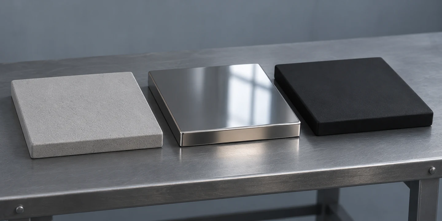
The finish and orientation of the actual part determine whether the receiver can identify the intended spot. These swatches illustrate three finishes worth testing separately.
| Target or condition | Optical risk | How to qualify the head |
|---|---|---|
| Light matte paint or ceramic | A strong return at one setting may clip at another, and texture can shift readings as the spot moves | Check response at near and far positions, over representative texture and at the chosen acquisition rate |
| Dark rubber or coated metal | A weak image can increase scatter or cause missing measurements, especially when exposure time is limited | Run the darkest allowed finish at full speed and record both accepted values and invalids |
| Polished metal or glossy curved plastic | A narrow return can move away from the receiver or saturate it as the surface normal changes | Test the full angular envelope in the head's prescribed diffuse or direct-reflection geometry |
| Clear glass, film or translucent polymer | Returns from different interfaces, transmitted light or subsurface scatter can move or split the detected image | Move the intended face by a known amount, vary the background and verify which interface the head tracks |
| Alternating finishes or wet and dry parts | The optical response can change even when height is constant. Exposure changes may also affect transition behavior | Pass a production sequence with the same height across finishes, then repeat with known physical steps |
| Dust, mist, oil or nearby illumination | A window can lose transmission, and stray reflections or ambient light can compete with the desired return | Compare clean and expected operating conditions with the final shield, window and neighboring equipment in place |
Look at the optical diagnostic if the device provides one. A weak peak, clipped peak, changing background or two plausible peaks can explain distance shifts even when the reported value stays within range. A plastic part can broaden the received peak through penetration, which is one reason some heads have a material-specific setting. For a clean test, place two finishes in the same plane and translate them under the beam. Compare the reported change with an independent height check. An apparent step at a material boundary is evidence to investigate the return or mounting before adjusting the reject threshold. Micro-Epsilon optoNCDT 1320 operating instructions
A head designed for direct reflection can suit a controlled mirror-like surface when its emitter, receiver and target are aligned in the geometry specified by the manufacturer. A different laser wavelength can help on some targets, including certain translucent or glowing materials, depending on optical penetration and background light. Some blue-laser heads also use dedicated direct-reflection optics. Check the target and required interface using the exact model. For transparent thickness, require a head or system explicitly designed to separate the relevant interfaces and account for the material and geometry. Micro-Epsilon blue laser and direct-reflection examples
Fit the spot and the receiver view to the feature
Spot size defines the area that contributes to the return. Distance resolution describes the size of a depth change the head can discern under specified conditions. A head can distinguish a small change in distance while its spot is much wider than the feature the station is supposed to measure. On a step, two levels can contribute to one detector image. The output can switch between levels, fall between them, or become invalid depending on which returns reach the receiver and how the sensor interprets them.
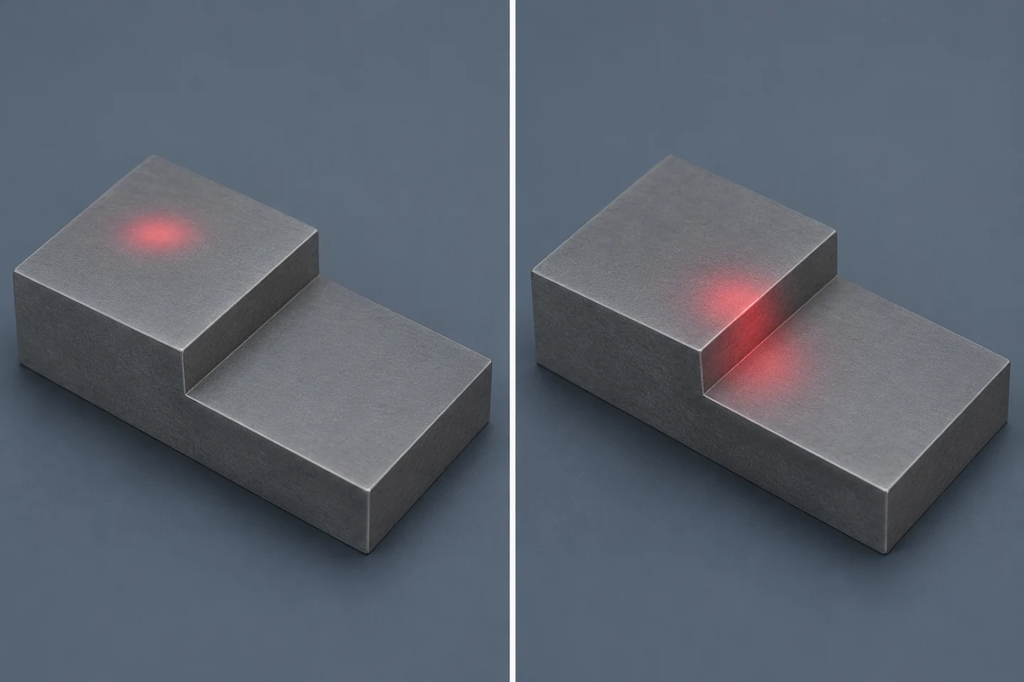
Use samples from the terrace interior for step height. When illumination spans the edge, the reported value depends on the competing returns and the head's processing.
Use the footprint dimension along the direction in which the feature crosses the beam. A quoted diameter typically uses a defined light intensity and leaves some light outside that boundary, so a nearby bright edge can still influence a nominally centered measurement. For an elliptical spot, this depends on head orientation. Tilt can also enlarge or move the projected footprint. Include placement variation across guides or fixtures and allow room for the real transition, such as a chamfer, radius or burr. Measure those allowances on production parts. Rotating a head may improve the footprint orientation, but also rotates the receiver's view. On a rough continuous surface a broader footprint can reduce sensitivity to individual texture peaks, while on a narrow land it can erase the useful measurement window.
At a recess, a clear path for the emitted beam establishes only half the geometry. The offset receiver also needs a view of the illuminated area. A wall can block that view at one end of the gap range or when the part drifts in the guide. Check the optical drawing in plan and side elevation with the worst expected part pose. Where changing the head orientation is allowed, try placing the receiver along the recess and verify that both paths stay clear. For a rotating cylindrical part, start near the intended radial line and test axial wander, eccentricity and surface angle over a revolution. Panasonic's product guidance shows examples for moving steps, rotating objects and recesses. The drawing of your selected head determines the installation orientation. Panasonic HG-C mounting guidance
Calculate how many useful samples the line can capture
For a conveyor at constant speed, divide the line speed by the effective sample rate to get the distance traveled between samples. Use the rate available to the logic evaluating the feature. A head can acquire at several kilohertz while the controller reads only the latest result once per scan. If the sensor or a data module buffers every sample with its timing or encoder position, a slower controller can still use the higher rate. Confirm whether the data stream contains every acquisition, decimated updates or repeated values. Distinguish output cadence from response delay.
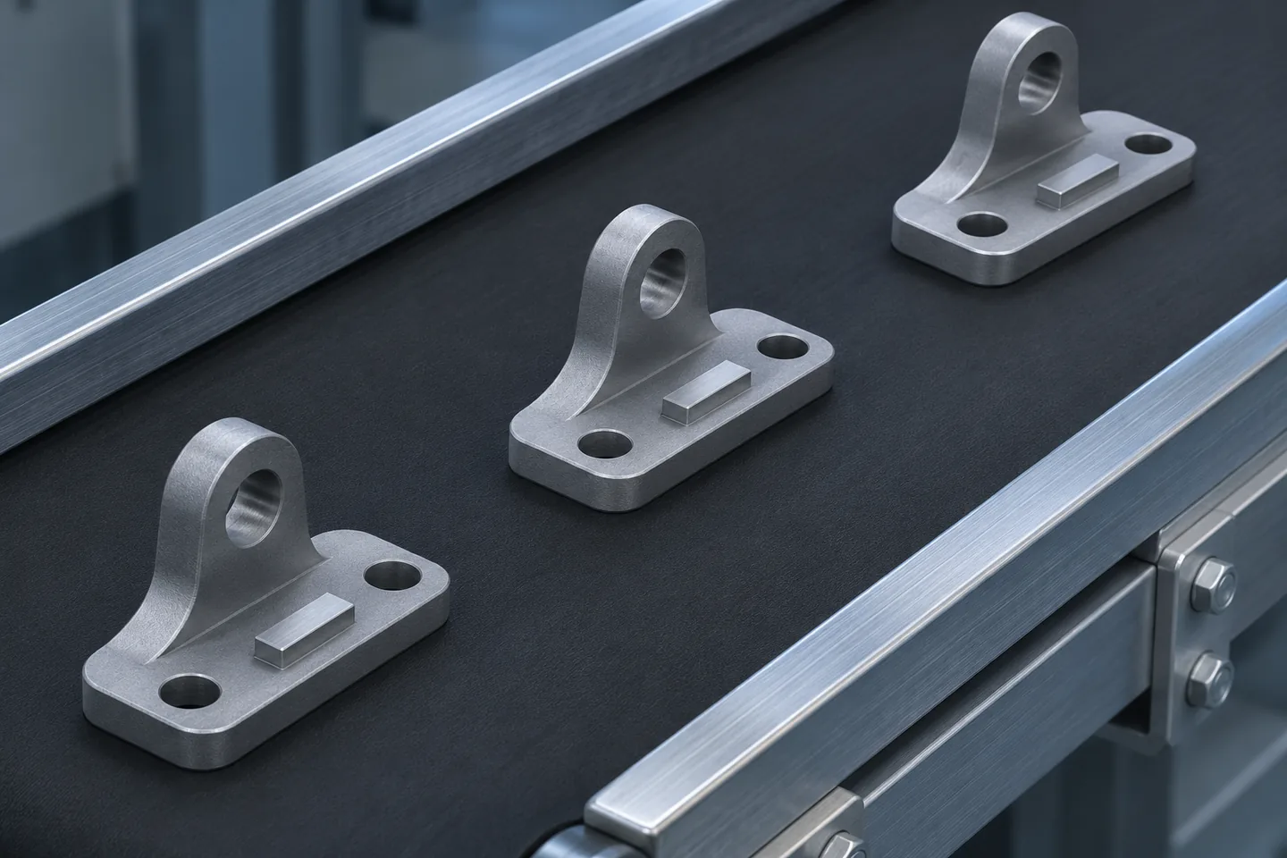
Only the interior of each moving pad is available for a top-height estimate. The controller also needs separate measurements on the lower datum surface if the reported value is step height.
Consider a station measuring a step on a machined part moving at 600 mm/s. The upper land is 1.60 mm long along travel. At the worst allowed distance and orientation, assume the footprint along travel is 0.40 mm. Reserve a further 0.10 mm at each edge for uncertainty in registration and for the edge transition. For this design example, the intended sample centers are kept at least 0.20 + 0.10 = 0.30 mm from each edge. The usable length is 1.60 − 2 × 0.30 = 1.00 mm. The lower terrace needs its own usable window, worked out the same way.
At 4,000 delivered samples per second, the spacing is 600 ÷ 4,000 = 0.15 mm. With uniform spacing and no dropout, there are at least six nominal sample centers in the 1.00 mm window regardless of sample phase. At 1,000 delivered samples per second, the spacing is 0.60 mm, giving only one guaranteed nominal center. A recipe that needs several valid measurements per feature would be sensitive to phase at that rate, even if stationary repeatability is excellent.
Now suppose the head uses a four-sample causal moving average, updated at each acquisition. At 4,000 samples per second, the centers of the first and last samples in each average are three intervals or 0.45 mm apart. For every contributing sample to lie inside the 1.00 mm usable window, the positions of the newest samples span only 0.55 mm. With the same ideal timing assumptions, only three fully supported output updates are guaranteed. Adjacent averages also share samples. Three smooth updates do not give the same statistical evidence as three independent measurements. A station can use an unfiltered stream, collect valid samples by position and calculate a robust result within each terrace window. Bench data can show how much filtering is necessary.
A four-point moving average at this rate shifts the center of its support back by 1.5 sample periods, or 0.375 ms. The full system can add exposure, transfer, input conversion and processing time. If a completed measurement reaches the controller 3 ms after the associated target position, the part has moved 1.8 mm at 600 mm/s. Matching such a value to the current conveyor position can move the gate off the pad entirely. Measure delay end to end with the intended signal path. Where timing matters, capture the encoder position or a synchronized timestamp at acquisition. An encoder tied to the belt still needs a check for part slip or an independent part trigger.
Check exposure time on the darkest approved target at maximum speed. The part moves during each exposure, so the return can include motion across the finish or edge even when the sample centers seem adequately spaced. If exposure is automatically adjusted, compare the relevant settings or diagnostics on bright and dark lots and across the transition between them. Allow for jitter, delays and invalids before deciding that a marginal sample count is acceptable. Set the acceptance gate and minimum valid sample count for each terrace. If either terrace lacks enough valid data, route that part through the inspection system's defined unresolved-measurement path.
Handle invalid measurements at the output
Ask how the exact model reports too little light, saturation, range errors, or a disconnected link. Some heads provide a fault status or distinct output value. Others can be configured to keep the last valid distance for a number of cycles. An unchanged plausible distance can therefore be stale. For example, the optoNCDT 1320 manual documents both explicit error output and modes that retain the last value. Confirm how the configured behavior appears at the actual controller input. Micro-Epsilon optoNCDT 1320 operating instructions
Log validity or error state alongside the distance, trigger position and timestamp where supported. Check whether a held value is marked as held, whether the hold counts acquisition cycles, and whether the PLC can distinguish freshness when communications stop. For an analog connection, verify scaling, input range, noise and the response to the manufacturer's specified error signal. For a digital connection, verify units, sample counters or timestamps, and behavior when frames are missing. Try a known target loss during commissioning and check what the final decision logic records.
Mount the head and prove the assembled measurement
Choose a short, stiff mounting arrangement tied to the machine datum. An independent support that moves relative to the part can look like real target displacement. Check bracket movement with actuators cycling, under changing cable loads and as equipment warms. A stationary target referenced to the machine frame can help separate sensor or fixture motion from part variation. Tighten to the head and bracket manufacturer's mounting instructions and provide repeatable locating features if the head must be removed for service.
Keep both optical paths accessible for cleaning and protection. A shield can stop stray light yet obstruct the receiver at the far position. A protective window can add reflections, contamination or a geometry change, so test the installed window and its exact orientation. Verify that nearby heads do not interfere when they run together. Carry the model's installation instructions and laser classification into the machine's integration review.
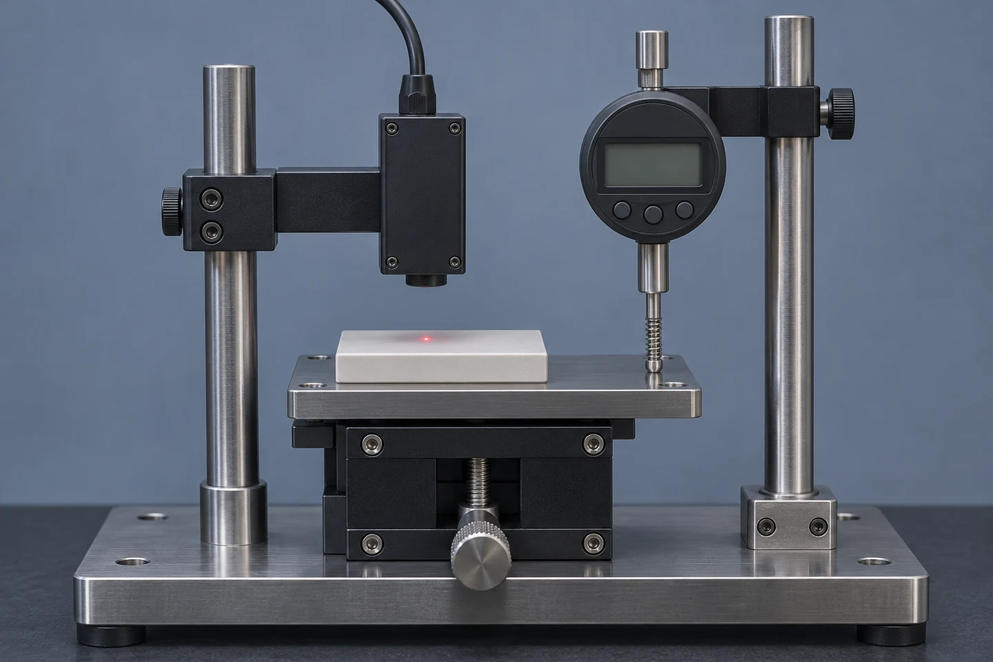
On a bench, the target and the indicator contact point move on the same rigid stage. Minimize pitch and check that the indicator and laser locations undergo the same displacement.
Start with a stationary check using a suitable independent reference, such as a calibrated stage read by an indicator with adequate uncertainty, or a dimensionally characterized step artifact. Check more than one position and approach positions from both directions. Use the same fixture and geometry as the installed measurement where practical. With a stage, keep the reference and laser tracks close enough that stage pitch contributes little to the difference. A large separation between the reference and laser contact lines can turn a small rotation into an apparent difference in travel. Record the reference method and uncertainty alongside the results.
Zeroing against a known part aligns one point. It can correct an offset at that position while leaving a slope error, a range-dependent deviation or a surface-related bias. After zeroing, verify near, nominal and far positions with independent references. Return to nominal at the end of the sequence to check drift or seating. Then repeat with representative parts, since the artifact's finish can give a cleaner optical signal than the surface encountered on the line.
| Commissioning trial | What to vary | What to record and compare |
|---|---|---|
| Stationary reference moves | Near, middle and far positions, approached from both directions | Reference, mean reading, bias and repeat spread at each position |
| Production finish and pose | Finish extremes, direction of brushing, target tilt, lateral shift and representative lots | Apparent height at matched reference, diagnostic signal and invalid count |
| Dynamic feature run | Slow through full speed, different trigger phases, realistic spacing and filter settings | Minimum usable samples per window, measured step and controller delay |
| Machine state and environment | Warm-up, vibration, lighting, neighboring heads, window installed and reasonably representative contamination | Reference drift, noise, changes in invalid rate and interruptions |
| Decision path | Known acceptable and unacceptable features, borderline values, missing target and stale readings | Final decision, part identity, error state and handling of inconclusive cases |
Set the acceptance limits from the actual task before running these trials. A displacement feedback loop needs evidence on delay and the usable motion bandwidth. A quality station needs a defined allowable error, minimum valid sample count, an invalid-measurement policy and evidence that the decision remains reliable near its tolerance limits. Track invalid samples by feature and by part. A small average invalid rate can hide a recurring failure on exactly the short feature used to make the decision.
If results deteriorate only at production speed, compare the raw signal, the processed distance and the values stored by the controller. Raw returns that break up near the edge point to optics or geometry. A clean unfiltered distance trace followed by a rounded processed plateau points toward filtering. A clean sensor stream paired with values at the wrong part position points toward timing, data association or loss in the receiving system. If a fixed reference moves whenever an actuator starts, inspect the structure and reference fixture before re-tuning the filter.
Retain the model, firmware, mounting position, setup file, light mode, sample rate, averaging, output scaling and validity behavior with the measurement record. Mark the reference surface and selected part windows in the machine documentation. A head replacement, fixture change, added protective window or new finish should prompt a repeat of the checks those changes can affect.
Întrebări frecvente
Can one laser displacement sensor measure both black and shiny parts?
A single head may handle both if the darkest finish provides enough signal at line speed and the brightest or glossiest finish remains interpretable across the allowed angles. Test the sequence of finishes as well as each one separately. Some exposure settings that help on dark surfaces change the response near a boundary. Measure bias and invalids at the production rate with the same settings and optics the machine will use.
Can I measure a 0.2 mm-wide feature with a sensor that repeats to 1 µm?
Only if the effective footprint, part placement and receiver view leave a usable region on the feature, and the line delivers enough valid samples in that region. The 1 µm figure describes repeated distance measurement under stated conditions. It gives no direct evidence about the minimum feature width. Start with the spot dimensions over the installed gap and allow for edges, motion and alignment.
Does using a longer range make a sensor easier to install?
A longer range can absorb more variation in gap, but the head may have a different working distance, larger spot or larger absolute linearity error. Compare individual models at the same relevant distances and finish. If the bracket and part motion are well controlled, a shorter range with adequate margin may give a better fit. Where setup variation forces a larger range, check that the smallest feature remains measurable at both ends.
Why is the distance stable but wrong?
A steady value can be a biased return from a transparent interface, a wrong reference offset, a scaling error, or a held result after lost signal. Move the intended surface by a known amount and check the raw diagnostic, validity and final controller value together. Then change the background or nearby reflective surface while holding the intended target fixed. A correct output should follow the intended surface through those checks.
Can I average two head readings to remove sheet motion?
For thickness with opposing heads, use the calibrated separation minus the sum of the two inward-facing gaps. Both heads must observe the corresponding area at the same time for common vertical motion to cancel. On a tilted or moving sheet, unequal lateral locations or delays add apparent thickness changes. Compare the pair against a known thickness over the expected motion, angle and speed.
What should I ask a sensor supplier to demonstrate?
Provide part samples, drawings of both optical paths, allowable distance and tilt, minimum feature width, line speed, tolerance and the intended controller interface. Request a demonstration of distance error, response and invalid handling with the exact optics and output settings at the extremes. Ask for raw or diagnostic data where available and verify the proposed setup on the production fixture. A stationary result on a demonstration target answers only part of the selection question.





lasa un raspuns