
Choose a tilt sensor by defining the physical angle, the equipment's motion while that angle is needed, and the allowable error and delay at the installed mounting point. A static inclinometer is appropriate when external acceleration is sufficiently small during measurement. A dynamic inclinometer combining acceleration and angular-rate measurements can improve tracking during movement, but its performance must be checked against the actual motion. Neither display resolution nor a smooth output proves that an installed angle is correct.
The most useful first question is whether the machine needs an angle continuously or only after it stops and settles. That distinction can change the required sensing system more than choosing a finer numerical resolution. Define the operating states before comparing product specifications.
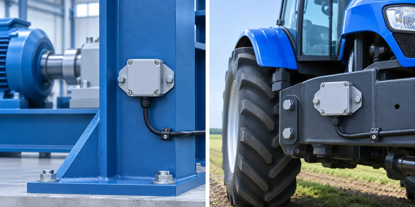
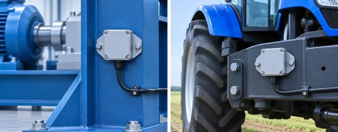
Stationary leveling and inclination during travel impose different measurement conditions. The equipment scenes illustrate those conditions, without representing a particular product or test.
Start with the angle the equipment actually needs
An inclinometer normally reports inclination relative to gravity. A machine controller may instead need a joint angle, the angle between two moving parts, or an angle relative to a surveyed installation reference. Those are different measurements. A sensor on a vehicle chassis does not directly report the angle of a hinged attachment, and a sensor on the attachment does not directly reveal the joint angle when the chassis also tilts.
Write a one-sentence requirement: “Measure the cross-slope of this rigid frame relative to horizontal during these operating states.” Replace “this” and “these” with named parts and states. Then identify where the sensor can be mounted and whether that location remains mechanically representative under load. A thin cover panel may move differently from the structural member that matters.
If the required quantity is relative rotation around a shaft, evaluate a shaft encoder or another joint-position measurement. Gravity-based inclination may still be useful for checking the assembly's orientation, but it answers a different question. Choosing the reference first avoids trying to solve a geometry problem through calibration alone.
Also distinguish a continuous angle measurement from a binary tilt switch. A switch can indicate a configured event; it does not necessarily provide an angle that can be logged, compared across positions or used for proportional control. Specify whether the controller needs a number, an event or both, and how it should identify an unusable measurement.
Define axes, signs and units
Use a drawing to connect the sensor's marked axes to the machine coordinate system. Record positive directions and the zero position. The words pitch and roll are useful only after their conventions are defined. Suppliers can use different angle representations, and the angle associated with a named axis may refer to rotation about that axis or inclination of that axis.
A three-axis accelerometer does not automatically supply three independent absolute orientation angles. Gravity provides a vertical reference, but it cannot identify rotation around that vertical direction. Heading therefore requires other information if it is needed. The ifm technology explanation illustrates this limitation and its angle conventions.
Keep units explicit through the entire controller chain. Percent slope is 100 multiplied by the tangent of the slope angle, rather than the angle in degrees. As a mathematical example, a 10% slope corresponds to approximately 5.71 degrees. This conversion describes geometry; it is not a permissible operating slope for any machine.
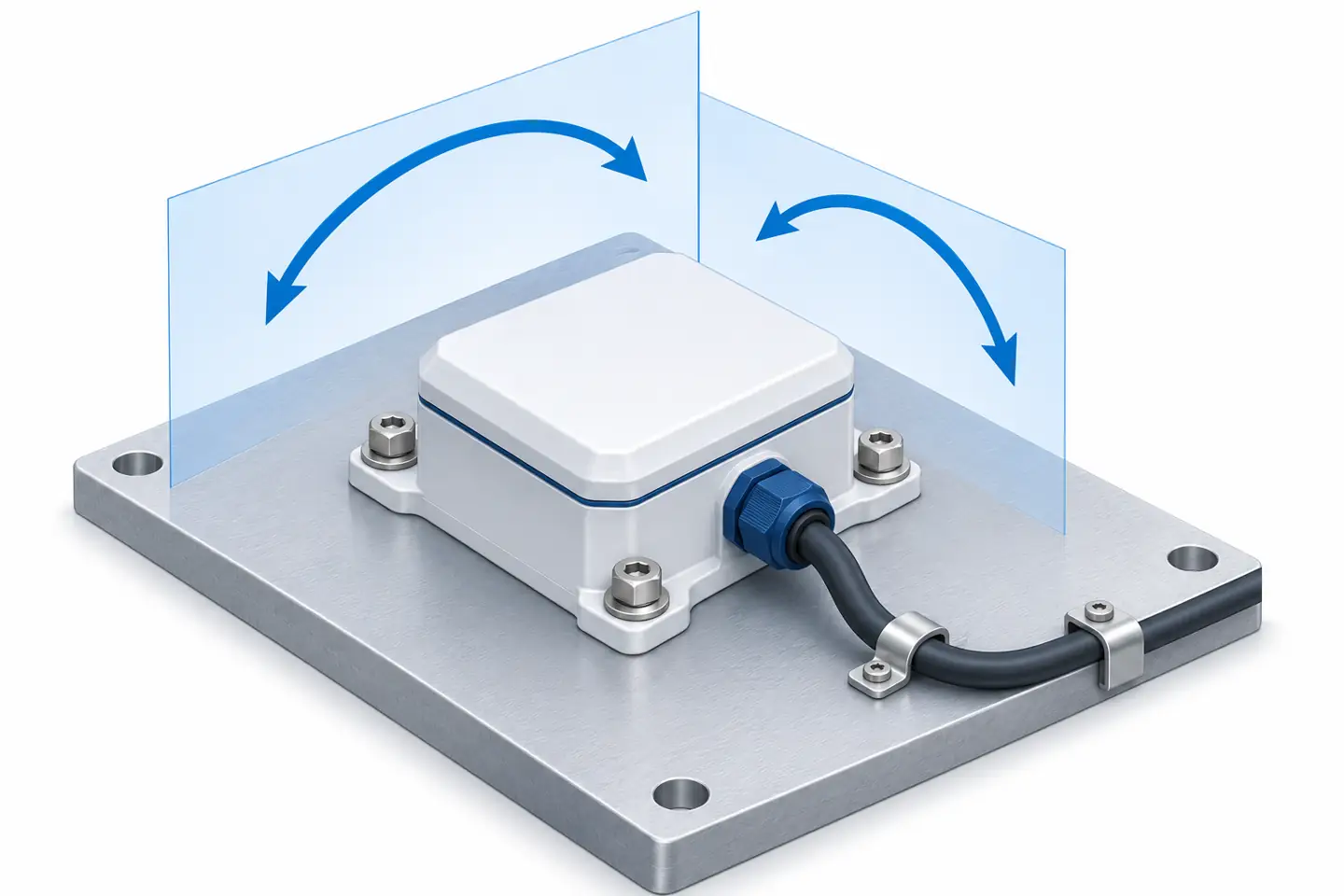
The two arrows indicate distinct tilt directions. Their mapping to output variables must follow the selected sensor's coordinate definition.
Why acceleration can look like a change in tilt
An accelerometer measures specific force. In a stationary installation, its axis outputs contain the components associated with gravity, allowing an angle calculation. When the installation accelerates, those outputs also change because of motion. A calculation assuming gravity alone can interpret part of that change as tilt.
The essential limitation is an ambiguity in the information available, rather than merely random electrical noise. Braking, starting, turning and vibration can all matter. Constant speed in a straight line differs from acceleration, but a vehicle moving at constant speed around a curve still experiences acceleration. The word “moving” alone therefore does not fully specify the measurement condition.
Analog Devices AN-1057 explains gravity projection and the effects of added acceleration. For a simple conceptual example, assume a level platform, horizontal acceleration of 0.05 times gravitational acceleration, and a two-component angle calculation that treats all measured force as gravity. The magnitude of the resulting apparent angle is approximately arctan(0.05), or 2.86 degrees. This is an ideal calculation, not a measured product error or a recommended acceleration limit.
The example shows why a sensor with excellent stationary accuracy can produce an unsuitable signal during motion. It also explains why specifying more decimal places does not fix the problem. A finely resolved measurement can faithfully describe the wrong apparent angle when the underlying assumptions do not hold.
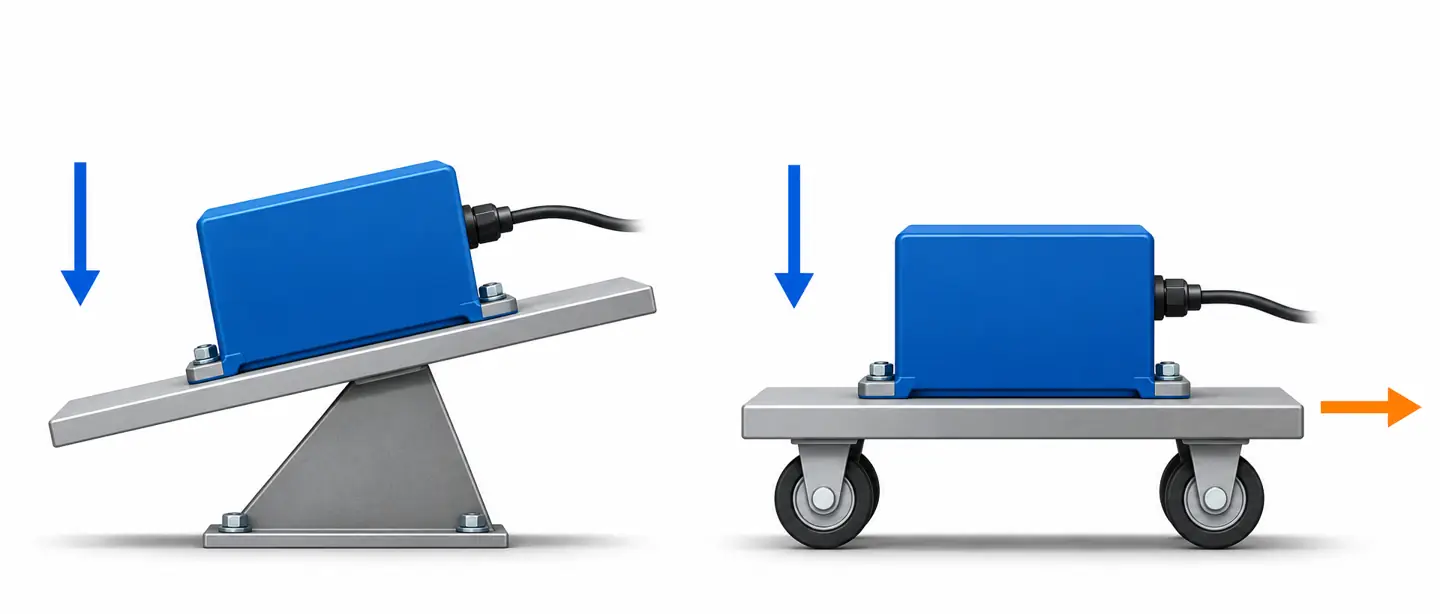
Vertical blue arrows represent gravity; the horizontal orange arrow represents added translational acceleration. The illustration distinguishes the causes without showing measured vectors or numerical data.
Filtering trades disturbance reduction against response
A low-pass filter or moving average can reduce some rapidly changing disturbance. It also changes the response to a real change in inclination. If the angle is needed only after settling, that trade-off may be acceptable. If the controller must follow a changing angle promptly, excessive smoothing can undermine the measurement's usefulness.
Averaging does not reliably distinguish sustained acceleration from gravity. Nor should a quiet signal during vibration be assumed unbiased. Sensor behavior, mounting and signal processing need to be evaluated together. Record the exact filter configuration during comparison tests; changing it changes the measurement behavior, even if the hardware remains the same.
A useful acceptance exercise separates two questions: does the output remain sufficiently accurate when the physical angle is constant and disturbance is present, and does it follow a genuine angle change within the required time? Checking only one can select a setting that fails the other.
Choose static or dynamic sensing by operating state
Static inclinometers use a gravity reference under static or quasi-static conditions. MEMS acceleration sensing is common, while fluid, electrolytic and pendulum approaches also exist. These technologies have different implementation details; none should be selected solely because a technology name sounds more precise. Compare complete instruments under the relevant conditions.
A dynamic inclinometer commonly combines accelerometer data with gyroscope data and an estimation algorithm. Angular rate helps track short-term rotation, while the gravity reference helps constrain longer-term inclination. Integrating angular rate alone accumulates error when bias is present. Fusion manages these different strengths and limitations rather than creating an unlimited independent reference.
The TE Connectivity sensor-fusion paper discusses this approach and emphasizes reduction of short-term acceleration effects. Performance still belongs to the particular system and motion conditions. Ask how it behaves through extended acceleration, repeated turns, vibration, startup and recovery from disturbance, rather than accepting “dynamic” as a complete specification.

The proof-mass and rotation symbols represent measurement functions combined in an estimator. This is a functional concept, not the internal construction of a named device.
| When the angle is needed | Starting approach | Evidence required before acceptance |
|---|---|---|
| After a stationary frame has settled | Static inclinometer | Installed error, repeatability and settling at relevant temperatures |
| On a slowly repositioned assembly | Static or dynamic, depending on allowed delay | Angle error during movement and after stopping |
| During vehicle starts, braking and travel | Dynamic system qualified for that motion | Transient error, lag, recovery and measurement-validity behavior |
| During long periods of acceleration or complex rotation | Application-specific orientation system | Manufacturer limits, needed aiding information and representative comparison tests |
| Only for a configured tilt event | Suitable switch or measurement-plus-controller arrangement | Event repeatability, hysteresis and defined invalid-signal behavior |
The same machine can occupy several rows. A mobile machine may use stationary inclination for setup but require a different estimate during travel. The controller must know which measurement conditions are satisfied. A stop command is not by itself proof that vibration and mechanical settling have ended.
Read accuracy specifications as a set of conditions
Resolution is the smallest output increment. Repeatability describes how consistently an instrument returns to a condition. Accuracy specifications address agreement with a reference under defined conditions. These properties are related but not interchangeable. A sensor can return nearly the same biased result repeatedly, or provide many numerical increments inside a larger error band.
Ask which errors the accuracy number includes: initial offset, scale factor, nonlinearity, cross-axis effects, temperature, calibration uncertainty or other terms. Identify whether the number is typical or guaranteed, whether it applies across the full range, and whether it describes static testing. If the datasheet is ambiguous, record the missing condition rather than silently interpreting it favorably.
The Analog Devices MEMS selection guide identifies bias, temperature behavior, noise, repeatability and vibration rectification as important inclination considerations. Its named-device examples should not be transferred to an unrelated packaged sensor. The purchasing specification should describe the delivered instrument, including its configured processing and interface.
Range and angle geometry
Specify the full required operating envelope, including installation offsets and expected movement in both axes together. “Two axes” does not automatically mean that the full single-axis range is available in every combined orientation. Ask for the angle definition and any invalid regions or singular positions.
Check output behavior around boundaries. A value that changes from a positive limit to a negative limit may represent a wrap convention rather than a physical jump. A controller calculating differences must handle that convention appropriately. Test near the positions the equipment will actually reach, including transitions across any representation boundary.
A sensor selected for a narrow range around level should not be assumed equally effective near a very different orientation. AN-1057 explains that the sensitivity of a single-axis gravity projection changes with angle. Complete multiaxis products may use different calculations, so verify their specified usable envelope instead of applying one formula to all devices.
Temperature and long-term behavior
The operating temperature range tells you where a device is intended to operate; it does not automatically guarantee the headline accuracy throughout that range. Separate electronics survival, measurement validity and compensated accuracy. Include cold startup, warming under power and temperature changes if those occur in the application.
Temperature can also change the physical mounting angle. For structural monitoring, that movement may be part of the quantity being studied. Removing a correlation between temperature and angle can accidentally remove real structural behavior. The Leeman Geophysical documentation explicitly discusses temperature effects on calibration and mounting-surface expansion.
Keep baseline readings and independent reference information before applying corrections. If the aim is to separate sensor drift from structure movement, an isolated single trend is usually insufficient evidence. Plan the reference checks and mounting inspections that will allow those explanations to be distinguished later.
Allocate error to the installed system
The sensor is one contributor to the final result. Mounting alignment, bracket deformation, reference uncertainty, output conversion and controller processing can also matter. Begin with the maximum error the application can tolerate and reserve room for these contributors before choosing the sensor specification.
For an illustrative stationary requirement of 0.5 degrees total allowable error, a proposed conservative allocation might reserve 0.2 degrees for the sensor, 0.1 for installation alignment, 0.1 for structural effects and 0.1 for reference and conversion effects. These are hypothetical allocations, not product specifications. They show that buying a sensor with a 0.5-degree limit would leave no allowance for the rest of that example system.
Do not combine every error by root-sum-square without understanding its statistical meaning and independence. A persistent mounting offset and a persistent temperature-related bias can act in the same direction. For an acceptance decision, state whether the budget is a worst-case bound, an uncertainty analysis or an empirical comparison under defined conditions.
Include delay and data validity in the specification
An update rate describes how often a value is delivered. It does not fully describe how old the underlying information is or how rapidly the angle follows a change. Internal filtering, estimation, transmission, polling and controller processing all contribute to the usable response.
Ask for a step-response description or a time-domain comparison under relevant motion. Specify whether the controller uses every sample, a periodically polled value or another average. Where multiple sensors are compared, synchronize timestamps sufficiently for the intended analysis; a timing mismatch during movement can appear to be an angle disagreement.
Check startup and fault behavior deliberately. Does the device report an initialization state? Can a communications outage leave the last valid value on screen? How are out-of-range or invalid angles represented? A plausible stale number can be harder to detect than an obvious missing value, so the receiving system needs a freshness check appropriate to its task.
The Pepperl+Fuchs contribution in CAN Newsletter illustrates angle-validity flags and configuration for a particular dynamic product. This demonstrates the kind of information to request, rather than establishing that every inclinometer provides the same diagnostics.
Mount and connect the sensor as part of the measurement
Use a rigid, repeatable mounting surface on the part whose angle matters. Follow the product's specified fasteners, tightening guidance and mounting orientation. An enclosure bolted to a flexible bracket can correctly report the bracket's motion while poorly representing the machine frame. Check the bracket under relevant loads, rather than only while the machine is unloaded.
Keep cable forces from moving the sensor or its support. Provide strain relief and route the cable so routine motion does not pull on the connector. Inspect mounting surfaces for debris, uneven contact and changes caused by maintenance. A repeatable alignment feature can make future replacement easier to verify.
Avoid adding a soft isolation pad simply because the signal is noisy. Isolation changes the mechanical connection, and the resulting movement may alter the relationship between the sensor and the object. If isolation is needed, evaluate its transfer behavior and angle stability in the actual installation. Begin by identifying the disturbance and checking a rigid mounting option.
For electrical integration, verify supply limits at the sensor, connector pin assignments and the receiving input's requirements. With an analog signal, confirm the documented angle-to-output mapping and inspect conversion in the controller. With a digital interface, verify signed values, scaling, units, byte interpretation, identifiers and status information against the device documentation. Matching connector shapes does not establish compatibility.
An enclosure protection rating also has conditions. Confirm the intended connector, cable and installation arrangement for the actual exposure. Water ingress protection alone does not establish resistance to chemicals, connector damage or cable fatigue. Write the environmental requirement in terms of the installed assembly and maintenance conditions.
Three examples of selecting around the real task
Stationary machine leveling
Consider a hypothetical processing frame that is adjusted during installation and then checked while stationary. The initial candidate can be a static inclinometer, because the useful reading is taken after adjustment has settled. The acceptance plan should cover mounting repeatability, the range around level, temperature conditions and agreement with a suitable independent reference.
The important distinction is between leveling the sensor and leveling the frame. A convenient zero button can hide a mounting offset without showing that the frame is physically horizontal. Establish the reference first, record the offset and verify several positions. If the machine runs during monitoring, add the operating vibration condition to the assessment.
Mobile equipment during travel
For a hypothetical agricultural vehicle needing cross-slope information while driving, a stationary accuracy check is only the beginning. The comparison should include representative starts, stops, turns and surface disturbances within an approved test plan. A dynamic inclinometer may provide a more useful signal, but the criterion is angle error and delay during those events.
Compare the sensor on the same rigid body as the independent reference. Record motion, mounting position, configuration and timestamps. If the reference is another accelerometer-only tilt unit, both may show similar acceleration-related error; agreement between them does not establish true angle. Choose reference equipment whose performance is adequate for the dynamic comparison.
Slow structural change
For a hypothetical long-term monitoring point on a support structure, short-term resolution is only one requirement. The plan must preserve reference direction, temperature history, mounting condition, power interruptions and service records. A change in reading could arise from real movement, mounting disturbance or sensor behavior.
A zero reset should therefore be a documented event rather than a routine way to tidy the trend. Keep the original baseline and explain any replacement or correction. A single local angle also does not describe the entire shape or condition of a structure; measurement placement and interpretation must match the actual monitoring question.
Verify the instrument before relying on its output
Begin on a controlled bench with an independent angle reference suitable for the required comparison. Its uncertainty and fixture stability must be adequate for the acceptance criterion. Do not use an unverified phone display as the sole reference for a precision claim.
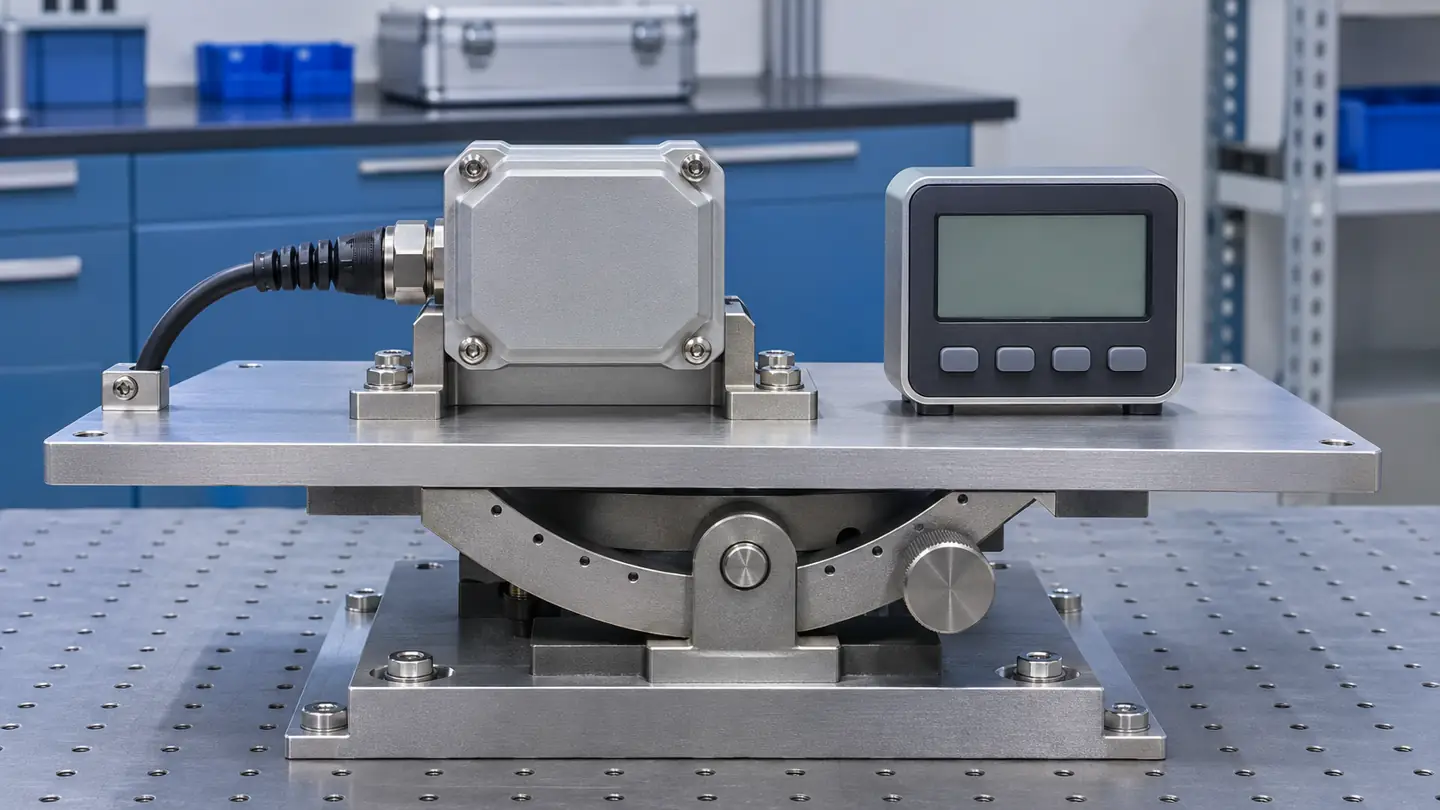
Both instruments share the same rigid reference plane. Blank displays avoid implying measured results; the appropriate reference depends on the required accuracy and motion.
A practical verification sequence is:
- Record device identity, firmware, angle mode, range, filter settings, output configuration and reference equipment.
- Check the zero position against the reference without immediately forcing a zero adjustment. Preserve the original result.
- Apply several known positions across the required range, approaching them from both directions. Repeat relevant combined-axis positions.
- Observe the return to zero, repeatability and settling after movement. Check controller values as well as any local display.
- Repeat the relevant checks after remounting or power cycling when those events are part of normal use.
- Add temperature and representative motion conditions required by the application, using suitable reference equipment and an approved setup.
- Compare the results with the written acceptance limits for error, delay and validity, and save the complete configuration with the decision.
A bench pass establishes only the conditions tested. Repeat key checks after installation, because the bracket, cable, power supply and receiving software are now part of the chain. Do not compensate an unexplained discrepancy until the reference, geometry and units have been checked.
Troubleshoot the pattern before changing the calibration
| Observed behavior | Possible explanation to investigate | Useful separating check |
|---|---|---|
| Similar offset at many stationary positions | Mounting zero, reference mismatch or sensor offset | Compare defined reference planes before applying zero |
| Error changes across range | Scale, angle convention or nonlinearity | Compare multiple independently known positions |
| One axis changes when only the other is moved | Axis misalignment, geometry or cross-axis response | Verify coordinate definition and fixture movement |
| Error appears mainly during acceleration | Gravity-motion ambiguity or estimator limitation | Compare stationary and dynamic reference results |
| Signal looks stable but follows late | Excessive filtering or communication/controller delay | Compare timestamped response to a real angle change |
| Trend follows temperature | Sensor temperature behavior or real mount movement | Compare controlled reference and mounting evidence |
| Value freezes without an obvious fault | Stale data, communication loss or display behavior | Check freshness and diagnostic status at the receiver |
These are diagnostic possibilities, not conclusions from a single symptom. Change one relevant condition at a time and retain the earlier results. A zero correction can hide an offset, but it cannot repair an axis convention, remove a flexible bracket or establish dynamic performance.
A requirements worksheet for comparing candidates
Use the same completed worksheet for every candidate. It makes omitted conditions visible and gives acceptance testing a clear target.
| Requirement | Ce să înregistrezi |
|---|---|
| Measurement definition | Named rigid body, reference plane, axes, signs, zero and units |
| Operating states | Stationary, repositioning, travel, turning and relevant transitions |
| Angle envelope | Individual and combined-axis range, boundaries and invalid regions |
| Measurement quality | Required installed error, repeatability and temperature conditions |
| Time behavior | Allowed delay, settling, startup and recovery behavior |
| Mechanical installation | Mounting location, rigidity, fasteners, cable support and replacement alignment |
| Electrical integration | Supply, output scaling, protocol, status and freshness handling |
| Mediu inconjurator | Temperature, vibration, shock, exposure and connector arrangement |
| Verificare | Independent reference, tested positions, motion conditions and pass criteria |
| Lifecycle | Baseline records, configuration backup, inspection and re-verification triggers |
For component-level choices such as acceleration range, noise and acquisition bandwidth, see the Sensor1stop accelerometer selection guide. Bring those choices back to the complete angle requirement before selecting the final instrument.
Întrebări frecvente
Can a static inclinometer work on a moving machine?
Sometimes, if the required reading is taken under conditions with sufficiently small external acceleration and suitable settling. Steady straight-line travel differs from turning or braking. Define when the reading is used and verify those conditions instead of classifying the application by vehicle speed alone.
Is a dynamic inclinometer always more accurate?
No. It can improve angle tracking during certain motion, while a static instrument may satisfy a stationary task with simpler integration. Compare installed accuracy, delay, temperature behavior and configuration under the same conditions. The dynamic label alone does not rank two instruments for every application.
Can filtering replace a gyroscope?
Filtering can reduce some disturbance but also delays real changes and cannot reliably remove sustained acceleration. A gyroscope adds angular-rate information, which is different from smoothing the same acceleration measurements. Whether that extra information is needed depends on the motion and response requirement.
Does factory calibration remove the need for installation checks?
Factory calibration addresses the delivered sensor under specified conditions. Installation introduces a mounting reference, mechanical behavior and a receiving signal chain. Verify those elements, even if no additional sensor calibration is necessary. Preserve the manufacturer's calibration and distinguish a mounting-zero adjustment from a full calibration.
What angle should trigger a machine safety stop?
There is no universal trip angle for a tilt sensor. A permissible operating condition depends on the equipment, load, configuration and its engineered protection system. Sensor selection must follow that system's defined measurement and diagnostic requirements. An accurate angle output alone does not establish a complete safety function.
When should a tilt sensor be checked again?
Use the equipment's verification plan and evidence from service conditions. Replacement, remounting, impact, unexplained drift, firmware changes or changed filtering can justify another check. Record the event and compare with the retained baseline so that a changed measurement is not mistaken for a changed machine angle.






lasa un raspuns