
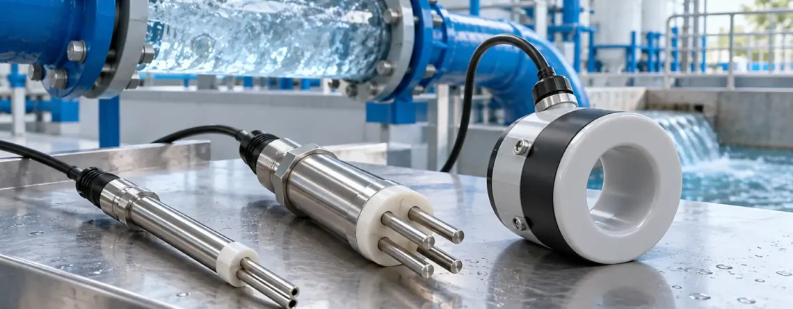
Choose a water conductivity sensor from the expected conductivity range, water chemistry and installation, then verify the cell constant and temperature treatment before interpreting the number. Two-electrode, four-electrode and inductive sensors all measure electrical behavior of a liquid, but they do not have the same strengths in ultrapure, ordinary and heavily fouling water. A reading in µS/cm is only comparable to another reading if the temperature basis, instrument configuration and sample conditions are known.
This guide is for aqueous samples and process water. It focuses on the questions a buyer, operator or engineer must answer to make a reading useful: what the sensor actually measures, where it sees the water, how its geometry affects the result, what compensation means, and how to verify the installed system. It combines the valuable questions in two older broad conductivity drafts into one practical measurement guide.
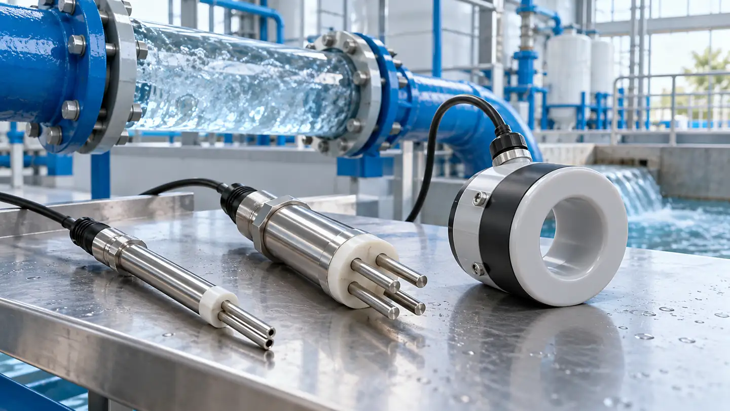
Define the decision before picking a probe
Conductivity is useful as a quick indicator of ionic change. It can reveal that water composition has shifted, support deionization or rinse monitoring, identify a process transition, or help track salinity-related changes. It does nu identify which ions are present. Two different mixtures can have the same conductivity. It cannot by itself certify drinking-water safety, identify contamination chemistry, or replace a direct measurement of a particular nutrient or disinfectant.
Write the operating question in one sentence. “Detect breakthrough after an ion-exchange bed” implies a low range and a sampling point after the bed. “Confirm completion of a cleaning rinse” implies a changing range and possible temperature and chemical transients. “Trend cooling-water concentration” implies a more conductive, possibly fouling liquid and a probe that survives the installation. These uses may share units but need different sensor construction and data interpretation.
| Measurement job | Main selection concern | Typical interpretation limit |
|---|---|---|
| High-purity water trend | Low-range sensitivity, cell cleanliness, temperature model and sample contamination. | A small change can come from a tiny contamination in the sample path. |
| Drinking or environmental water | Representative sample, calibration range and temperature reference. | Conductivity does not identify contaminant species. |
| Industrial rinse or CIP transition | Wide range, chemical compatibility, rapid response and fouling. | A single threshold may change meaning as chemistry and temperature change. |
| Saline or concentrated process stream | High-range performance, polarization or electrode-free design, materials. | Conversion to salinity or TDS depends on the actual mixture. |
The best probe is the one that measures the decision range with an acceptable error in the actual liquid, not the one with the widest advertised span.
What the instrument measures
In an aqueous solution, dissolved ions carry charge. A conductivity instrument applies an alternating electrical signal to a cell and measures conductance. The cell constant represents the geometry that links measured conductance to conductivity. In a simplified ideal cell, conductivity equals conductance multiplied by a cell constant expressed in reciprocal length, often cm⁻¹. Real probe geometry is more complex, so the effective constant is determined and verified for the manufactured sensor. A wrong programmed constant can produce a plausible but systematically wrong display.
Conductivity is commonly shown in µS/cm or mS/cm; 1 mS/cm equals 1,000 µS/cm. Resistivity is its reciprocal under consistent units and is often used for very pure water. A display that switches between conductivity, resistivity, salinity and “TDS” may be applying different calculations to the same electrical measurement. TDS estimated from conductivity is a conversion with a solution-dependent factor, not a direct measurement of the mass of every dissolved substance.
The Analog Devices conductivity measurement article explains the relation between cell geometry, conductance and temperature sensing. The YSI conductivity overview describes how cell constant and temperature compensation influence water measurements. These principles are stable, but the usable range and accuracy belong to the particular cell and meter pairing.
Two, four and inductive electrodes answer different needs
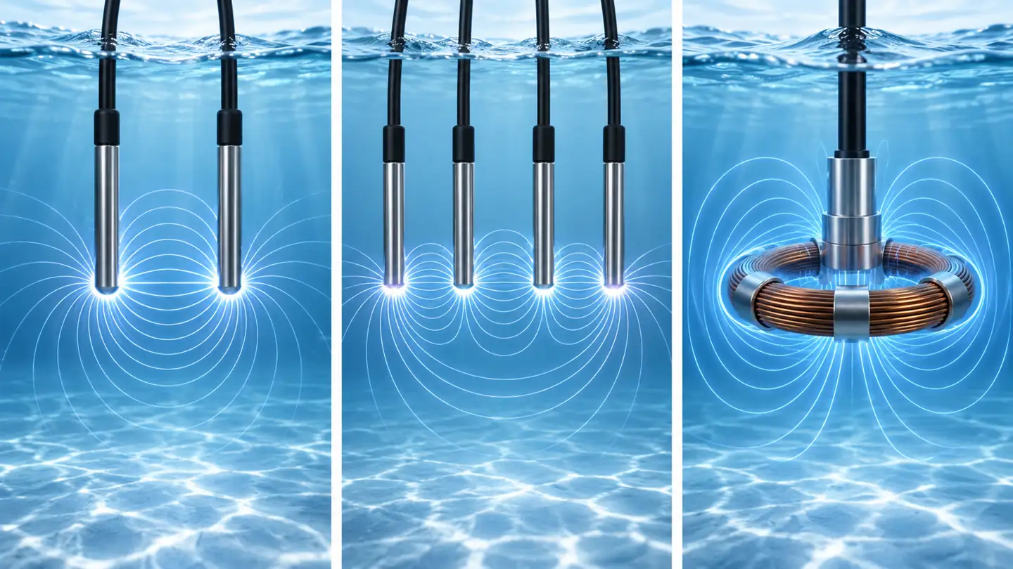
A two-electrode contacting cell drives and measures through the same electrode pair. With a suitable geometry it can be very effective at low conductivity and in clean water. At higher conductivity or with coating, the electrode interface and polarization can contribute more error. A small cell constant often supports a lower range, but that is a design tendency rather than a universal numerical boundary; check the complete probe's specification.
A four-electrode contacting cell uses separate drive and sensing electrodes. This reduces the effect of electrode polarization and contact resistance on the measured voltage and can offer a broad operating range. It still has wetted surfaces that may foul and must be matched to the liquid. A four-electrode label does not make a probe suitable for every chemical, pressure or temperature.
Un inductive or toroidal cell transfers energy through the liquid without bare measurement electrodes contacting it. It can be attractive in dirty, coating or corrosive service when the specified materials and range suit the process. It generally is not the default choice for very low-conductivity water because the induced signal becomes small. Installation geometry matters: a toroid close to a pipe wall or in a small fitting may require the manufacturer-specified clearance or calibration method.
The Yokogawa contacting-sensor guide lists polarization, contamination, cable resistance and temperature among error sources, and shows how ranges change with cell constant. The Hamilton selection guide compares two- and four-pole applications. These are useful comparison frameworks, but model-specific materials and ranges remain decisive.
Cell constant: the configuration people miss
A probe marked 0.1 cm⁻¹ and a transmitter configured for 1.0 cm⁻¹ do not form a correct measurement pair. Even if the display responds smoothly to changes, the scale can be wrong. The cell constant also changes effectively if geometry is damaged or deposits alter the electrical path. Some systems store the value in the sensor, others require it in the transmitter, and some accept a calibration-derived adjustment. Document which value is nominal, which is currently programmed, and which was obtained from the last accepted verification.
To compare two instruments, confirm they report the same quantity and units, use compatible temperature compensation, and are measured in the same water. An inline probe and a beaker probe may see different temperature and dissolved-gas exposure. A long sample line can contribute contamination or allow a transient to pass before the comparison is made. If a reading appears off by a large factor, inspect units and cell constant before replacing the sensor.
The Mettler Toledo conductivity theory guide surveys cell technologies, while the Yokogawa conductivity specification provides a concrete example of different constants and ranges within one product family. Avoid copying a range from one constant to a different one. The geometry, electronics and reference conditions belong together.
Temperature: actual conductivity versus a reference value
Ionic mobility and, in some waters, chemical equilibria change with temperature. A meter may display actual conductivity at the sample temperature sau specific conductance corrected to a reference temperature, often 25 °C. These are different quantities. If one trend is compensated and another is not, a difference may be caused by configuration even when the water is identical.
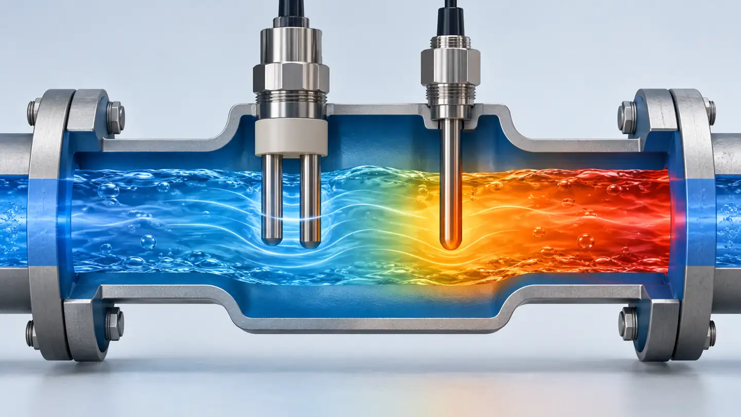
Many general-purpose meters use a linear temperature coefficient. The often-quoted “about 2% per °C” is a rough description for some waters near ordinary temperature, not a universal law. The coefficient depends on the dissolved ions, concentration and temperature. Ultrapure water behaves differently from saline water or concentrated cleaning chemicals. Dispozitive analogice discusses why conductivity measurement needs temperature information, while YSI emphasizes the chosen coefficient and reference basis.
Compensation should be recorded with its reference temperature and method. A transmitter might offer a fixed linear coefficient, a salt-specific model, a nonlinear high-purity-water model, or no compensation. Select the mode required by the process method or the actual solution. Do not turn on a generic correction just because it makes a result look familiar. If a formal testing method requires uncompensated readings at measured temperature, follow that method. Also check that the temperature element is measuring the same water at nearly the same time as the conductivity electrodes.
Where to install the probe
An inline cell should contact representative flowing water without trapped air, stagnant pockets or deposits that prevent exchange. A beaker measurement should allow the probe to be immersed to its specified depth and kept clear of the container wall if the geometry requires it. A bypass stream introduces its own tubing, flow and delay. Different flow conditions can change fouling and temperature, even if conductance itself is measured electrically.
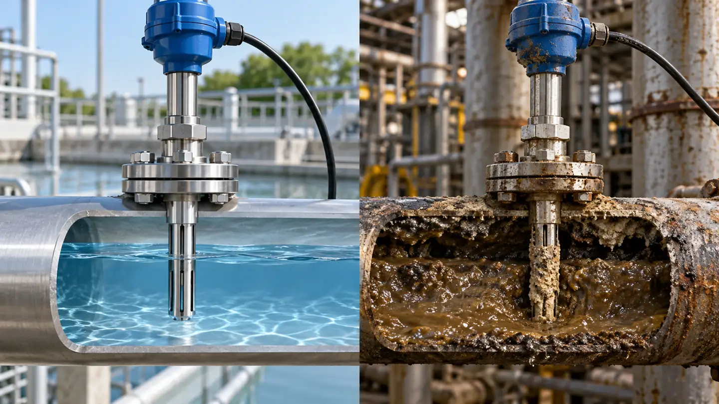
For a high-purity process, sample contamination may dominate. Small residues in a beaker, atmospheric exposure or leaching from tubing can produce a meaningful change in conductivity. A flow-through design may better preserve the process sample when the instrument and method require it. For a heavily fouling or corrosive process, prioritize wetted materials, cleaning access and a cell style that tolerates deposits. A chemically compatible probe can still read incorrectly if the flow cell traps bubbles or lacks the clearance specified for an inductive sensor.
Record the process point and the sensor's actual environment: maximum and ordinary temperatures, pressure, flow, chemical excursions, solids, cleaning agents and whether the probe can be removed safely. A water-treatment sensor often serves for years only if it can be cleaned and verified without damaging its electrodes. The installation drawing should show the measurement point and its isolation or bypass arrangement, not merely a generic probe symbol.
Calibration and a meaningful verification
Use a conductivity reference solution appropriate to the expected measurement range and the manufacturer’s method. The reference has a certified value at a specified temperature. Bringing a cold probe into a warm standard and immediately accepting the first number combines temperature and electrical transients. Allow the probe and standard to reach the conditions described by the method, and avoid contaminating the standard by repeated use or poor rinsing. Keep a record of its identity, lot and expiry if supplied.
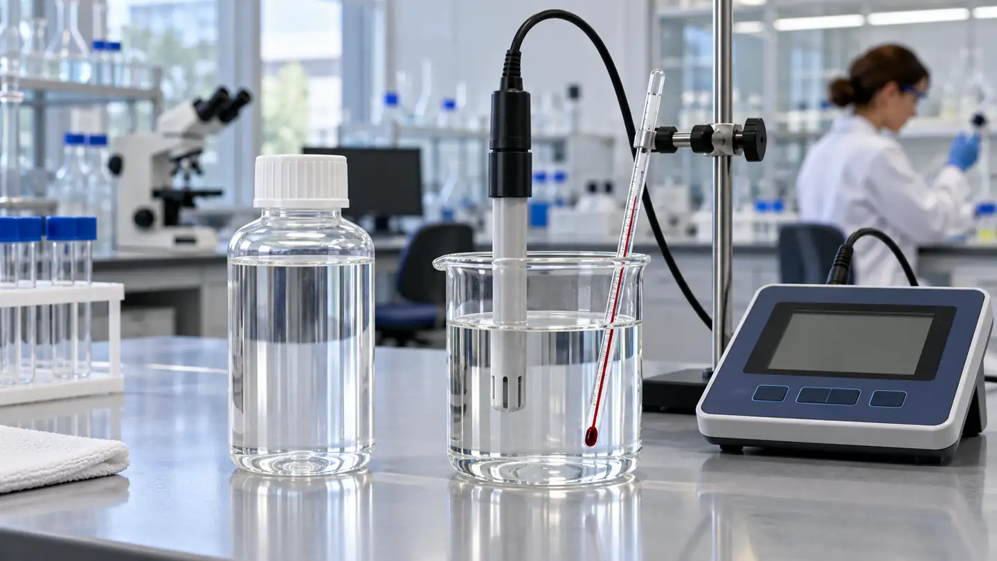
Distinguish verification din adjustment. Verification asks whether the as-found instrument reads an accepted reference within the allowed tolerance. Adjustment changes a cell constant or calibration factor when the procedure permits it. Record the as-found value before editing the transmitter; otherwise a later reviewer cannot tell whether a process trend reflected changing water or instrument drift. After adjustment, confirm the result and return to normal configuration.
The standard should be near a relevant part of the operating range. A high-conductivity standard may be a poor test of a very low-range probe, and a low one may not reveal high-range polarization. If the process spans orders of magnitude, a single point may not test the entire application. Check whether the sensor and meter are specified as a pair, whether a factory cell constant is stored, and whether the test procedure calls for one or several standards. The Mettler Toledo laboratory conductivity sensor guide describes cell selection and calibration concepts; apply the method for the actual instrument.
Diagnose readings in the right order
When a conductivity trend jumps, first inspect the process and sample: a valve change, regenerant breakthrough, cleaning chemical, temperature shift or new water source may be real. Compare actual and reference-temperature displays if available. Then check units, cell constant, compensation mode, temperature channel, bubbles and flow. A dirty or damaged probe is one hypothesis, not the first assumption every time.
If two probes disagree, place them in the same stable sample under the same temperature treatment before declaring one wrong. If they agree in a reference solution but disagree online, investigate sampling locations, flow, geometry and fouling. If a reading is inexplicably stable, confirm the probe is in fresh flowing water and the transmitter is not holding its last good value during a fault. Inspect the raw temperature and status as well as the compensated number.
For an inductive cell, a coating may change the effective path through the liquid and a mounting restriction can change the magnetic coupling. For a contacting cell, deposits or polarization can depress or destabilize the signal. Never use abrasive cleaning on delicate electrode surfaces unless the manufacturer specifically allows it. Compare before-and-after checks so cleaning does not mask a recurring process problem.
A purchase and commissioning worksheet
An example of how the wrong setting creates a believable error
Suppose a process engineer wants to compare conductivity at two points in a water line. The first transmitter displays the raw value at 20 °C, while the second displays a value corrected to 25 °C using a linear coefficient. Even if the water composition is identical, the two screens can disagree. If the probes also use different cell constants or the values are copied without units, the apparent “change” may be entirely a configuration difference. The correct first step is to record each instrument's actual water temperature, displayed quantity, reference temperature and compensation mode. Only then can the process team decide whether the water changed.
This example has no fixed numerical result because the difference depends on the solution and the correction model. It illustrates why a trend record needs metadata. A future analyst looking only at µS/cm values cannot reconstruct whether a seasonal temperature rise, a filter change or a transmitter replacement changed the reported quantity. Retain the configuration snapshot with the data historian tag, not only in a binder beside the instrument.
Special care for very pure and very conductive water
At the low-conductivity end, small contamination sources become proportionally large. A poorly rinsed beaker, air exposure, a sample valve that has not been flushed or leaching from tubing can affect the apparent value. The instrument and sample arrangement should minimize these effects, and the reference method should be designed for the range. In very pure water, the choice of temperature model is especially important because the water itself contributes to a nonlinear response; a generic coefficient used for ordinary water may be unsuitable. Ask the manufacturer for the model and conditions behind its high-purity specification.
At the high-conductivity end, electrode polarization, geometry and chemical compatibility grow in importance. A four-electrode or inductive cell may be attractive, but do not infer that either is automatically accurate in a concentrated chemical. Strong acids, alkalis, brines and mixed industrial liquids can have different temperature responses and may attack a probe's seal or fitting. Check the chemical compatibility of the entire assembly, including cable and holder, across normal service and cleaning excursions. A probe that survives a liquid is not necessarily correctly calibrated for it.
Conductivity can also be affected by concentration in a non-simple way. A mixture becoming more concentrated does not guarantee a proportional rise in displayed conductivity across every range, because ion mobility and chemistry change. A process that wants concentration should validate a conductivity-to-concentration relation for its known formulation and temperature range. For unknown water mixtures, report conductivity as conductivity. This prevents a convenient but unjustified “TDS” or percent-concentration label from acquiring false authority on a dashboard.
Build a verification record that distinguishes sensor from process
When an inline reading shifts, a second check should isolate possible causes. Record the current process state and compare a grab sample taken from a representative point with a portable meter under a documented temperature basis. Then check the inline system in a reference solution if the manufacturer's procedure permits removal. If the probe passes the standard but differs from the process sample, look at sampling point, flow, bubbles and local temperature. If it fails the standard, inspect configuration, contamination, damage and calibration history before making an adjustment.
The process and the reference solution are different tests. The standard evaluates the instrument against a known conductivity under specified conditions. The process comparison evaluates whether the installed instrument describes the water of interest. Passing one does not prove the other. A record should include both when a decision depends on the value. Preserve the as-found reading and any change to cell constant or temperature coefficient, then check the as-left state. Without the first reading, a calibration log cannot tell how much of a historical process trend might have been instrument drift.
Finally, check that fault and maintenance states are visible in the control system. A transmitter that freezes its last valid conductivity while a probe is removed can make a rinse sequence appear complete. Define what the display and output do on temperature-sensor fault, open circuit, out-of-range measurement and calibration hold. Verify those behaviors at commissioning. A water-quality number is useful only when operators know whether it is live, representative and within the instrument's specified envelope.
Before ordering, specify:
- Water and task: the process, expected low and high conductivity, contaminants, solids and the decision supported.
- Measurement basis: conductivity or resistivity; actual temperature or corrected to a named reference; any derived salinity or TDS calculation.
- Sensor design: two-pole, four-pole or inductive; nominal cell constant, wetted materials and compatible transmitter.
- Installation: inline, insertion, immersion or bypass; pipe and fitting geometry, flow, pressure, temperature and cleaning access.
- Performanţă: range, accuracy under stated conditions, temperature sensor, compensation modes and response in the complete installed system.
- Verification: standards near the working range, acceptance tolerance, as-found record and maintenance frequency.
- Controls: signal units and scaling, fault state, data logging and the action taken on an out-of-range value.
This worksheet makes competing proposals comparable. The lowest price per probe is less useful than knowing which configuration can hold an interpretable number in the real water and be maintained over time.
A useful handover note should explain what constitutes a normal variation for this particular stream. Conductivity can vary with feedwater blend, regeneration cycle, seasonal temperature and production recipe. A control limit copied from another plant may trigger constant nuisance alarms or miss a meaningful change. Establish the range from representative historical data and the process consequence, then check that the sensor's uncertainty and sampling delay are small enough for that decision. If the purpose is detecting a sudden breakthrough, record how long water takes to reach the probe and how quickly the transmitter updates its output. If the purpose is confirming a final rinse, make clear whether the acceptance limit is on actual or reference-temperature conductivity.
Maintenance access belongs in that handover as well. Identify where the probe can be isolated, how it is cleaned without altering delicate electrode surfaces, and which standard or comparison meter is used. Note any sensor replacement that resets a stored cell constant or temperature configuration. When the water chemistry changes substantially, revisit both the probe choice and the compensation model. An unchanged probe can become inappropriate for a newly concentrated or chemically different stream.
For long-lived installations, compare the maintenance burden of an inline probe with the cost of a sample bypass. A bypass may improve access and protect a delicate cell from pressure excursions, but it adds tubing, valves and a delay that can affect the decision. An inline sensor may observe the process directly yet be harder to remove without interruption. Document the intended verification route before the piping is built, and ensure a reference sample can be taken close enough to make a fair comparison. The preferred arrangement follows the process risk and service resources, not a generic diagram.
Întrebări frecvente
Does high conductivity mean the water is contaminated?
It means the water conducts more current, generally due to dissolved ions and temperature. It does not identify the ions or whether they are acceptable for the application. Compare with the relevant process baseline and use specific chemical tests when identity matters.
Is a four-electrode probe always more accurate?
No. It can reduce certain electrode-interface errors over a broad range, but a two-electrode design may be excellent for clean, low-conductivity water. Accuracy depends on the named probe, meter, range, sample and calibration conditions.
Should temperature compensation always be enabled?
Only when the comparison or method calls for a reference-temperature value and the compensation model fits the water. Keep actual temperature available. Some regulated methods require a specific treatment and should govern the configuration.
Can conductivity be converted directly to TDS?
The instrument can estimate TDS with a factor, but the factor depends on the composition of dissolved substances. It is not a direct gravimetric measurement and should be labeled as an estimate unless the process-specific relationship has been validated.
Why is the same probe different in a beaker and a pipe?
The two measurements may differ in temperature, sample freshness, atmospheric exposure, bubbles, nearby boundaries, flow or contamination. Check the installation instructions and compare in a representative stable sample with the same settings.
Primary references
- Yokogawa, Contacting Conductivity Sensors — contacting cell design, configuration and error sources.
- Analog Devices, Conductivity Measurement System — cell constant and temperature measurement principles.
- YSI, Conductivity in Water — cell and compensation interpretation.
- Hamilton, Conductivity Sensor Selection — technology comparison and application questions.
- Yokogawa, Conductivity Sensor Specification — example model-specific constants and ranges.








lasa un raspuns