
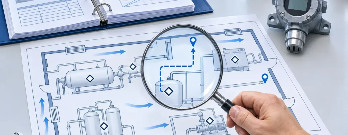
Gas detection coverage and gas detector response are separate claims. Coverage concerns whether the relevant release or atmosphere is likely to be observed by the detection arrangement under defined conditions. Functional and response verification concerns whether the installed equipment and interfaces perform the required action within the defined test and acceptance boundaries. A successful sensor check does not prove area coverage, and a coverage drawing does not prove that the alarm chain works.
A useful review therefore keeps three evidence threads distinct: the scenario and location basis, the equipment and response evidence, and the continuing availability of the required function. Connect those threads to the same defined protection objective. Without that common objective, a project can collect impressive maps, calibration certificates and commissioning sheets that do not establish the behavior it actually needs.
This article is a guide to reviewing design and acceptance documents. It does not prescribe detector spacing, alarm values, gas releases or a field proof-test procedure. Major-accident facilities, building systems, personal monitoring and confined-space work have different requirements. The responsible engineering and safety process must define the methods and acceptance criteria for the actual application.

Coverage review links identified sources, transport assumptions and candidate sensing locations. The plan and routes are conceptual, with no validated coverage boundary or installation dimensions.
Define the coverage claim before assessing it
A statement such as “the room is covered” leaves the gas, release, operating conditions and required action undefined. Begin with the intended duty: identify the substances and scenarios, the physical area or equipment, relevant operating modes, warning recipients and any required protective action. Coverage can then be assessed against that duty rather than against an arbitrary detector count.
For a point detector, the atmosphere must reach the sensing inlet. For a sampled system, it must reach the sample inlet and be delivered appropriately. For an open-path arrangement, the measurement has a defined path and reporting basis. These observations have different physical meanings. A symbol on a plan should identify what type of observation it represents.
Ask what the assessment means by detection. Is it reaching a stated concentration at a sensor, crossing an accepted alarm criterion, or achieving a particular number of responding detectors? If a voting arrangement is involved, the coverage method must reflect the required response logic. A plot showing one detector's observation cannot automatically support a function that depends on several independent inputs.
Also state exclusions. A layout designed for specified process release scenarios may not establish personal exposure along every route or atmospheric conditions inside separate equipment. Exclusions should be visible in the handover documents so that later users do not infer a broader duty. A bounded claim is more useful than a confident description that nobody can test or maintain.
Separate geometric mapping from scenario analysis
Coverage methods answer different questions. A geometric mapping exercise can evaluate how a defined reference cloud or target intersects a detection arrangement across an area. A scenario-based analysis can examine selected releases and conditions, including transport and dispersion assumptions. The terminology used by a project should be defined in its methodology rather than assumed from a report title.
TÜV Rheinland's discussion distinguishes reference-cloud mapping from modelling that considers release and dispersion variables. Its examples belong to their stated process context and are not universal cloud sizes or acceptance targets. The important review question is which assumptions create the reported coverage result. TÜV Rheinland: making the most of detector mapping.
A coverage percentage needs a denominator. What area, volume, set of locations or set of scenarios was assessed? Were locations weighted equally, or did scenario likelihood or consequence influence the result? Which operating modes were included? A percentage without those definitions can compare unlike studies and hide the precise gaps that matter to the application.
Do not confuse an assessment assumption with a physical protection radius. A circle, cloud shape or colored region may be useful within a particular method, but it does not establish the same distance for every gas, release and ventilation condition. Ask for the method, reference case, input data and limitations. If those cannot be explained, the graphic should not be treated as independent proof of coverage.
| Evidence type | Question it can support | Important boundary |
|---|---|---|
| Source and hazard assessment | Which events and consequences require attention? | Depends on the assessed scope and operating conditions |
| Geometric mapping | How does the defined reference target intersect the arrangement? | Reference target and denominator are assumptions to retain |
| Scenario or dispersion analysis | What happens for the selected releases and conditions? | Does not automatically represent unmodelled scenarios |
| Installation inspection | Does the installed arrangement match accepted documents? | Matching a drawing does not prove the drawing's basis |
| Gas-response verification | Does the sensor or sampled arrangement respond within the test scope? | A local challenge does not establish transport from every source |
| Interface or sequence verification | Do the included logic and output stages behave as required? | Excluded equipment remains outside the demonstrated result |
| Maintenance and impairment records | Is the accepted function available over time? | Records must match actual configuration and status |
Trace the route from source to observation
A coverage review begins before the sensor electronics. Identify the source and the path by which the relevant atmosphere is expected to reach the inlet or measurement path. Ventilation, obstacles, openings, release conditions and geometry can all affect that relationship. The evidence should use the actual configuration or explain the simplifications used.
Compare operating modes. A daytime ventilation state may differ from reduced operation, shutdown or a defined failure condition. An access door can connect another volume. Equipment and storage can introduce barriers absent from an early drawing. If the assessment depends on a mode or geometry, that dependency should appear in the assumptions and change triggers.
HSE's COMAH technical-measures document identifies positioning relative to release sources, dispersion, dilution, reliability and response among the considerations for leak and gas detection. It also highlights the risk of excessive reliance on ineffective detection. Its major-accident context should remain explicit when the principles are used to structure a review elsewhere. HSE leak/gas detection.
For a sampled arrangement, add the sample path to the route. A pump running or a flow indication does not by itself establish that the target substance reaches the sensor appropriately. HSE's CEMHD1-2020 alert describes adsorption losses in unsuitable tubing. The full path needs evidence for the intended substance and configuration, including the limitations of any verification performed. HSE sample-tube alert.

Observation depends on gas reaching the intended inlet and being delivered appropriately; this path is illustrative.
Define the beginning and end of every response claim
“Fast response” is incomplete unless the starting event, endpoint and conditions are stated. A sensor response specification may begin when a controlled gas change reaches the sensing region. A site response claim may begin with a release elsewhere and end with a warning or final equipment state. Those are very different intervals.
Trace the stages conceptually: release and transport, sample delivery where applicable, sensor response, instrument processing, communications, controller evaluation, warning or final-equipment response, and any required human action. The actual chain depends on the application. Do not add numbers from unrelated datasheets as though they describe one validated installation.
A T90 specification describes a defined fractional response under stated test conditions; it is not automatically the time at which an alarm operates. The relationship depends on the gas change, initial state, alarm criterion, instrument processing and other factors. A site acceptance record should use its own defined start and endpoint. Comparing two instruments by a bare T90 value can conceal different test conditions or channel configurations.
NIOSH Publication 2012-162 discusses performance evaluation of direct-reading monitors, including response, calibration, environmental effects and interferences. That instrument-evaluation framework does not establish a site's coverage or required protective time. It helps explain why performance claims need conditions and defined methods. NIOSH evaluation report.
The response budget should be established by the responsible assessment and design process. If a function must act before a particular consequence, the relevant timing and uncertainty need evidence. A generic article cannot select the required interval or define a safe margin for an unknown release. A reviewer can, however, identify a timing claim with no documented basis and request that it be resolved.
Match each verification activity to its purpose
Calibration, function checks, electrical simulations, interface checks and complete sequence tests should have explicit scopes. Their names alone are not enough. A calibration certificate might concern only the detector. A controller input test might bypass the sensor. A final-device test might be performed independently of the detection logic. Each record can be valuable while leaving interfaces unverified.
Ask which stages are included and excluded. For a sequence record, identify the initiating condition, instrument or input, controller logic, warning outputs and final equipment included. Where the test uses simulation, state what the simulation bypasses. Where a stage is demonstrated separately, explain how the combined evidence supports the intended sequence and where assumptions remain.
OSHA's SHIB 11-26-2024 distinguishes bump testing, calibration checking and full calibration for direct-reading monitors. It emphasizes manufacturer recommendations and suitable known-gas checks. That guidance is useful for understanding record boundaries, but it is not a universal fixed-system proof-test specification. OSHA monitor testing bulletin.
Avoid describing a test as successful unless its defined acceptance criteria were met and recorded. A response observed by one technician is not necessarily evidence for a time requirement, every channel or every alarm recipient. If timing was not measured, say so. If an external output was isolated, identify it. Honest boundaries make the record usable and prevent a later reviewer from attributing results that the test never established.

Detection, logic and downstream responses have separate evidence boundaries; the connections are conceptual.
Build an acceptance matrix instead of a stack of certificates
An acceptance matrix connects each requirement to the document or verification that addresses it. It helps expose requirements that have no evidence and evidence that does not support a stated requirement. The following structure is a review tool, not a field test instruction.
| Requirement to establish | Evidence category | Boundary to state | Open item if absent |
|---|---|---|---|
| Correct target-gas capability | Exact detector and sensor documentation | Model, variant, range and conditions | Unsupported gas or configuration |
| Appropriate source observation | Accepted coverage assessment | Scenarios, modes, geometry and exclusions | Unreviewed source or transport path |
| Installed location matches design | Inspection and as-built records | Inlet identity, orientation and accessories | Installation discrepancy |
| Suitable sample delivery | Complete-path documentation and applicable verification | Gas, tubing, filters and configuration | Loss or delay not addressed |
| Valid measurement and status | Instrument and interface records | Normal, fault, inhibit and unavailable states | Ambiguous receiving-system interpretation |
| Intended alarm logic | Approved configuration and sequence evidence | Threshold basis, voting and timing where relevant | Logic does not match requirement |
| Warning reaches intended recipients | Annunciation design and verification | Included locations and conditions | Unobserved or misunderstood warning |
| Final response occurs | Accepted interface and final-equipment evidence | Exact outputs and endpoints included | An unverified link in the response chain |
| Function remains available | Maintenance and impairment arrangements | Responsibilities, intervals and restoration | No owner for lost protection |
| Changes remain controlled | Change-review process and records | Triggers affecting original assumptions | Accepted evidence no longer matches plant |
Use a separate row when two requirements have different boundaries. For example, a local warning and an automatic shutdown may share a detector but rely on different downstream equipment. A single “alarm checked” entry can hide that difference. Identify the responsible parties and the condition under which the row can be closed.
Do not convert the matrix into a checkbox exercise. The purpose is to preserve the connection between the requirement and the evidence. A document can exist yet be irrelevant to the installed configuration. A record can be signed yet omit the required endpoint. The reviewer should be able to explain why each entry supports the claim, not merely confirm that a file is present.
Hypothetical example: coverage looks complete but timing is unresolved
Consider a hypothetical pump enclosure with a coverage study, installed point detectors and a controller that drives a remote warning. The study evaluates selected release scenarios under stated ventilation conditions. The installation inspection confirms that the detector tags match the accepted drawing. A maintenance certificate shows gas response at each sensor. No real customer project or test result is represented here.
During handover, the owner asks whether the warning occurs within the time required by the design. The existing documents do not answer the full question. The coverage study addresses selected transport scenarios, while the sensor certificates concern local checks. The controller's configured delay and the remote annunciation interface are not identified in the combined timing evidence. The system may be capable of the required response, but the available records have not yet established it.
The team creates an acceptance matrix. It retains the valid coverage and instrument records and assigns the missing interface and timing questions to the responsible engineering process. The accepted verification plan will define its own safe method, boundaries and criteria. The team does not improvise a release into the enclosure or claim that adding brochure response times closes the evidence gap.
A second review identifies a later ventilation change. The original study's assumptions may no longer match the enclosure. That change affects the coverage thread separately from the unresolved controller evidence. The matrix keeps both questions visible. Closing one does not close the other, and neither should be hidden behind a general statement that the detectors were “commissioned.”

A location assessment and a response check support different claims. The unscaled waveform is an illustration of a record type, not measured detector response.
Availability changes the practical meaning of coverage
A design assessment usually assumes a defined arrangement is available. A failed, inhibited or removed detector changes that arrangement. Whether the remaining function is acceptable depends on the original design and the authorized impairment assessment. Do not assume that a layout retains its accepted coverage because most of the symbols remain present on the drawing.
Where a response depends on voting or multiple channels, the effect of an unavailable input requires particular attention. The controller may have defined degraded-mode behavior, but its existence should be verified from the accepted configuration. A generic statement about redundancy cannot establish what the installed logic does. Identify the exact impairment state and the required site response.
Temporary monitoring arrangements need equally clear boundaries. A portable area unit may support a defined temporary duty, but it may not reproduce a fixed system's observation path, communications or automatic response. The impairment record should identify the differences, ownership, duration and restoration conditions. Avoid recording “portable supplied” as though it established equivalence.
HSE's functional-safety overview emphasizes lifecycle activities including specification, validation, operation, maintenance, proof testing and modification management for safety instrumented systems. Not every gas detection arrangement is an SIS, and no integrity level is assigned here. The broader review lesson is that accepted performance must be maintained and changes managed within the applicable framework. Siguranța funcțională HSE.
Changes can invalidate one thread while leaving another intact
A sensor replacement might preserve the location but change gas response or configuration. A new partition might preserve calibration while changing transport. A software revision might preserve physical coverage while altering status handling or output logic. Review the changed element and its dependencies rather than declaring the entire historical evidence either permanently valid or completely useless.
Define practical change triggers in the handover package: target gas, process conditions, release source, equipment layout, ventilation, sample accessories, detector model, alarm logic, communications and warning recipients. The list should reflect the actual system. Assign an owner who can decide which requirements and evidence need reconsideration.
Retain revision identities for the drawings, assessment, configuration and acceptance records. If these are scattered across different departments, the matrix can serve as the connecting index. The aim is to make it possible for a later reviewer to reconstruct the accepted arrangement without relying on someone remembering why a particular detector was installed.
The Sensor1stop overview of gas detector types provides background on instrument categories. A coverage review goes further: it connects the chosen measurement principle to a particular scenario and installed response. Technology selection, location assessment and functional verification each contribute evidence with their own limits.

Changes to equipment, airflow or configuration can require review of earlier detection evidence.
Test the evidence matrix with counterclaims
Before accepting a broad statement, ask what evidence would contradict it. If the claim is that all assessed sources are observed, look for a source or operating mode outside the model. If the claim is that the full alarm chain was demonstrated, look for an isolated output or simulated stage. If the claim is that the function remains available, look for an impairment or configuration change that the record does not address. This desk-review technique helps reveal hidden boundaries without prescribing a field test.
The exercise should remain fair to the evidence. A local sensor check is not defective because it does not prove dispersion; it was answering a different question. A coverage study is not invalid merely because it does not test a relay. The problem arises when the project attributes a broader result to either record. An acceptance matrix preserves the value of each activity while preventing that overstatement.
Ask the author of each assessment to state its strongest defensible conclusion in plain language. The conclusion should identify the configuration, scenarios, conditions and exclusions. If it relies on another report, identify the dependency. This is especially useful when several contractors contribute documents that use different equipment tags or drawing revisions. The final package needs a consistent account of the arrangement being accepted.
Keep measured, configured and assumed timing distinct
A response review may contain measured intervals, configured delays, manufacturer specifications and engineering assumptions. Label them separately. A configured delay can be verified from software but does not describe gas transport. A manufacturer response value can characterize an instrument under its test conditions but does not automatically describe the installed sample path. A measured interface interval can exclude the sensor if the input was simulated.
Do not present a total as measured when it was assembled from different kinds of information. If the engineering assessment combines stages, it should explain the method, conditions, uncertainty and applicability. If the project has not established a stage, leave it unresolved. An arithmetic sum can be precise while the underlying evidence is incomplete or incomparable.
The endpoint also needs care. A controller output changing state, a warning device operating and a final item reaching its required state are different endpoints. The accepted function determines which one matters. The record should not silently move the endpoint earlier in the chain because that point is easier to observe. If stages are checked separately, the combined acceptance argument must explain their connection.
Make closeout a technical decision
A document register can show that every file was delivered while important questions remain unanswered. Technical closeout should require the responsible reviewer to connect the files to the requirements. Identify which person or role accepts the coverage basis, instrument suitability, configuration, interfaces and continuing management arrangements. Different roles may accept different boundaries, but the overall ownership should remain clear.
When an open item is closed, retain the reason and supporting evidence. 'Reviewed' is less informative than a statement that the as-built inlet location was compared with the accepted assessment and the relevant discrepancy resolved. The record should explain the conclusion at an appropriate level without inventing details or implying tests that were not performed.
This approach is useful after an event as well as at commissioning. Investigators can distinguish a design assumption from a demonstrated behavior and identify where the installed arrangement differed from the accepted configuration. Accurate records do not guarantee an outcome, but they support a more reliable understanding of what the detection function was intended and shown to do.
Întrebări frecvente
Does a passing bump test prove coverage?
No. It demonstrates a response within the scope of that check. It does not establish whether a release at another location reaches the inlet under the relevant conditions. Coverage requires its own documented basis. Keep the gas-response record and coverage assessment as separate evidence that supports different parts of the overall function.
Is a coverage percentage enough to compare designs?
Only if the assessment basis is comparable and understood. Identify the denominator, reference cloud or scenarios, modes, geometry, detection criterion and exclusions. A higher percentage from a different method may not represent a better answer to the same hazard question. Compare the underlying requirements and assumptions before comparing the headline number.
Can T90 be used as the total warning time?
A sensor T90 value has defined conditions and endpoints. Total warning time can include transport, sample delivery, processing, communications and downstream response. The alarm may also operate at a different point on the response curve. Use a project-specific timing definition and appropriate evidence rather than treating T90 as a universal system time.
Is an electrical simulation an end-to-end test?
It depends on the stated boundaries. A simulation can verify included logic and outputs while bypassing gas access and sensing. Describe exactly what it demonstrates and what it excludes. Do not attach a broader label that implies untested stages were included. The combined acceptance evidence should show how the required function is established.
How should missing evidence be handled?
Record the unresolved requirement, the present evidence boundary and the responsible owner. Define what would close the item through the applicable engineering and safety process. An open item is preferable to an invented pass result or a generic certificate used beyond its scope. The final acceptance decision should reflect the actual evidence and remaining limitations.
How often should coverage be reconsidered?
Use the applicable management arrangements and change triggers for the system. A new source, ventilation change, barrier, sensor configuration or logic change can make earlier evidence less relevant. This article does not assign a universal review interval. The accepted plan should identify periodic review requirements and the events that demand earlier reevaluation.
Surse și domeniul de aplicare
- HSE leak/gas detection, COMAH technical measures, Great Britain.
- TÜV Rheinland detector mapping discussion, mapping and modelling distinctions; no universal target inferred.
- NIOSH Publication 2012-162, instrument performance-evaluation framework.
- HSE sample-tube alert, CEMHD1-2020, 10 September 2020.
- OSHA SHIB 11-26-2024, US monitor-testing guidance; not a universal fixed-system proof-test method.
- Siguranța funcțională HSE, safety lifecycle overview, with application boundaries stated above.







lasa un raspuns