
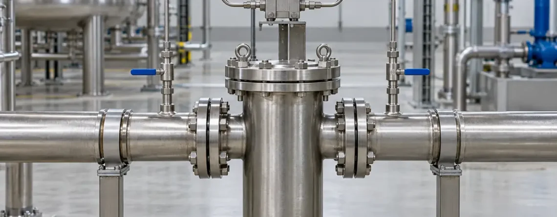
Choose a differential pressure sensor by defining the two pressure points, the useful differential range and the maximum pressure each port can experience. Then check accuracy at the operating point, medium compatibility, pressure taps, impulse lines and the way the signal will be verified. A device suitable for a few pascals across an air filter may be unsuitable for a small pressure drop in a high-pressure liquid line, even when both readings are called differential pressure.
Differential pressure is a difference between two pressures, not a direct measurement of filter cleanliness, flow or liquid level. A reliable system must bring representative pressure from each point to the sensor and correctly scale its output. This guide follows that measurement chain from the process taps to the displayed number.
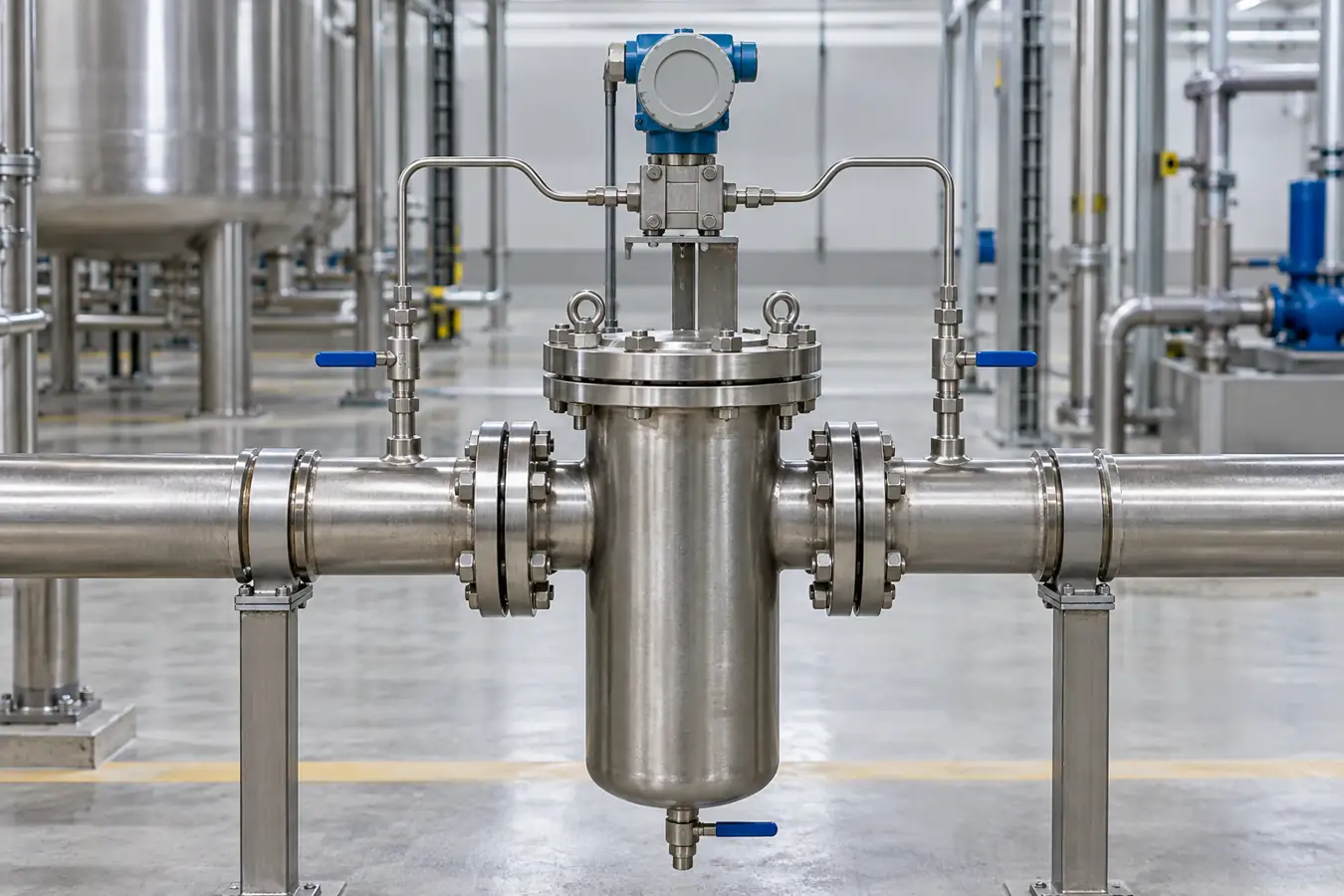
Define the two pressure points and the decision
For a differential transmitter with high and low ports, the reported differential is conventionally ΔP = P(H) − P(L). A positive result means pressure at the H port is higher than at the L port; a negative result means the reverse. The sign depends on the connections and the instrument's convention, so label both taps and the controller input.
A differential pressure across a filter may increase as resistance to flow increases. However, the reading also depends on flow rate, fluid properties and operating conditions. A higher value is not automatically proof that the filter alone has become blocked. Compare at similar operating conditions and use the equipment manufacturer's maintenance criteria.
| Измерительная работа | Pressure points | What the number can support | Additional information needed |
|---|---|---|---|
| Filter monitoring | Upstream and downstream of the filter. | Trend the pressure loss under comparable flow conditions. | Flow, medium, filter specification and operating state. |
| Room pressurization | Controlled room and a defined reference space. | Trend pressure difference and direction. | Door state, airflow and applicable facility criteria. |
| Flow element | Two taps across an engineered primary element. | Infer flow using the element's validated relationship. | Fluid properties, element geometry, installation and calculation. |
| Tank level | Appropriate liquid and reference-side pressures. | Infer hydrostatic head under a defined arrangement. | Liquid density, tap geometry, gas pressure and reference-line condition. |
For many differential-pressure flow elements, flow is approximately proportional to the square root of differential pressure under the conditions of the applicable calculation. It is not a universal direct one-to-one conversion. Near zero differential, offsets and uncertainty can have a large effect on inferred low flow. The primary element, fluid properties and installation must be considered along with the transmitter.
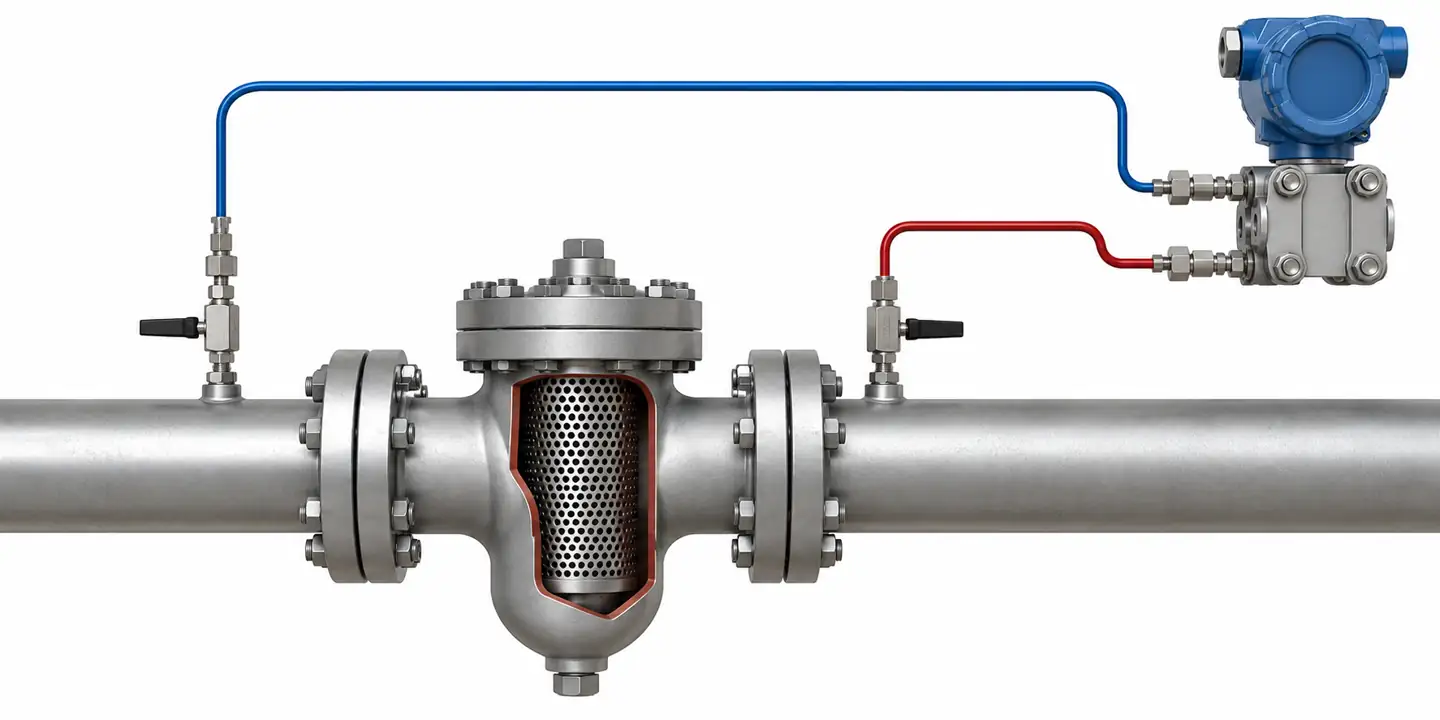
Separate measuring range from pressure resistance
The differential measurement span describes the difference the sensor is designed to measure. Static or common-mode pressure describes the pressure present at both ports together. A process can have a small differential while both sides are at high pressure. For example, an upstream pressure of 10 bar and a downstream pressure of 9.9 bar produce a 0.1 bar difference, while both ports still experience pressures near 10 bar. Those values are illustrative; they are not ratings for a particular device.
This distinction matters because a sensor may have an adequate differential span but an insufficient maximum working pressure or one-sided overload limit. During startup, shutdown, maintenance or a blockage, one port may experience a very different pressure from the other. Record normal and maximum pressure at each connection, expected transient conditions, maximum differential and manufacturer-defined limits. Never assume burst pressure is a normal operating limit.
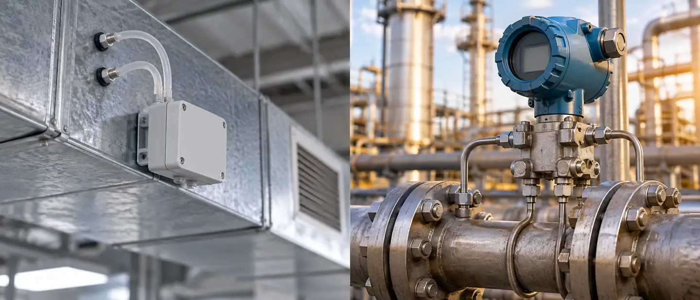
The Yokogawa EJA130E product information lists differential measurement, static pressure and pressure-limit information separately. Its published figures apply to the stated model and configuration; consult the exact specification for the selected capsule and option. A low-pressure air device such as the Johnson Controls DP150 is designed for a different building-control application. Similar labels do not make the devices interchangeable.
What to ask for in a specification
- Differential measuring range, including whether negative values are needed.
- Maximum working pressure and whether it applies to both ports together.
- Maximum one-sided differential or overload rating in each direction.
- Temperature and medium conditions behind the specified ratings.
- Pressure connection, wetted materials, sealing and mounting requirements.
- Reference accuracy basis, temperature effect, static-pressure effect and long-term stability.
- Output type, power supply, response time, electrical isolation and fault indication.
Manufacturers may use different definitions for “overpressure,” “proof pressure” and “burst pressure.” Use the definitions in the actual datasheet and do not substitute one for another. A sensor's ability to survive an exceptional event does not necessarily mean it remains accurate immediately afterward.
Select a useful differential range
Choose the narrowest range that covers the expected measurement and credible transients while meeting the device's pressure limits. An unnecessarily wide span can make a small working signal difficult to distinguish from offset, noise or a percentage-of-span error. A span that is too narrow can saturate during startup or process upsets and leave no useful indication of the event.
Start with a normal operating band and the decision point. A filter system might have a clean operating baseline, a maintenance decision level and a higher foreseeable upset. A room-pressure system may need to detect small positive and negative differences around zero. Ask whether the instrument supports a bidirectional range and how it reports readings outside the selected scale.
Some multi-range transmitters allow a field-selectable span. Confirm whether the accuracy claim changes with the selected range, whether the output is rescaled automatically and whether the controller must be updated. Record the setting on the transmitter and in the control system. A correct sensor connected to an incorrectly scaled analog input can generate a plausible but incorrect engineering value.
Read accuracy in the context of the actual signal
An accuracy expressed as a percentage of full scale or calibrated span is not the same as a percentage of reading. As a simple calculation, suppose a device has a ±1% of 100 Pa span reference accuracy under stated conditions. That component is ±1 Pa. At a 10 Pa reading, ±1 Pa represents 10% of that reading. This is arithmetic for an illustrative specification, not an estimate of a particular sensor's installed performance.
Reference accuracy may combine nonlinearity, hysteresis and repeatability under defined laboratory conditions. It may exclude temperature effects, static-pressure effects, mounting effects, drift, power supply and the uncertainty of the test reference. The Johnson Controls DP150 specifications identify the basis of the stated accuracy for that series. The WIKA CPT8900 specifications show that high-accuracy instruments can state separate static and differential characteristics. Compare like with like and check the actual model's conditions.
Do not automatically add every datasheet number as if all errors always occur in the same direction, and do not assume independent errors can always be combined by root-sum-square. A meaningful uncertainty budget depends on the specification definitions and application. For a critical decision, identify the dominant contributors and use a documented method appropriate to the project.
Static pressure and zero shift
When both ports experience a large common pressure, the transmitter can exhibit a static-pressure effect even if the differential is small. A zero check at atmospheric pressure may not fully describe behavior at the working line pressure. The Rosemount 3155 reference manual includes a model-specific discussion of high-static-pressure zero correction. The permitted procedure depends on the transmitter and process arrangement; use the actual manual and site procedure.
Repeatedly adjusting zero is not a substitute for finding a leak, blockage, unequal liquid column or changed installation. Before making an adjustment, record the as-found indication and establish that both ports genuinely see the intended equal pressure under the specified conditions. Preserve the as-left result and conditions for later comparison.
One differential sensor or two independent pressure sensors?
Subtracting two separate pressure measurements is possible, but each sensor contributes uncertainty to the result. Consider two transmitters that each read around 10 bar while the difference of interest is 0.1 bar. A small offset on either input can be a substantial fraction of the calculated difference, even though each individual pressure appears reasonable. The two channels may also have different temperature responses, drift or sampling delays.
A dedicated differential transmitter measures the pressure difference as its primary variable. It still has offset, temperature and common-pressure effects, and it must be rated for the pressure applied at each port. It is not automatically superior for every job: two sensors can be useful where individual pressures are needed or where their uncertainty is demonstrably acceptable. Compare the actual error budgets, installation and safety requirements for the intended decision.
For a subtraction in a controller, use compatible pressure references and synchronize the readings. Subtracting an absolute pressure from a gauge pressure without accounting for their different references is not a valid differential measurement. Also document what happens if one signal is missing or out of range; a controller should not silently treat a failed channel as a real zero.
The impulse lines are part of the instrument
Pressure taps, tubing, valves and fittings carry the two process pressures to the sensing element. A transmitter cannot correct a pressure that never reaches its port because a line is blocked, leaking or isolated. The location and condition of both taps therefore affect the meaning of the reading.
For a gas service, accumulated liquid can create unwanted hydrostatic head or a blocked path. For a liquid service, trapped gas can affect response and stability. Steam and high-temperature services often require arrangements determined by the equipment manufacturer and site engineering practice. Unequal liquid columns, temperature differences and long tubing runs can contribute offsets or delays. The precise design depends on the fluid, pressure, temperature and process safety requirements.
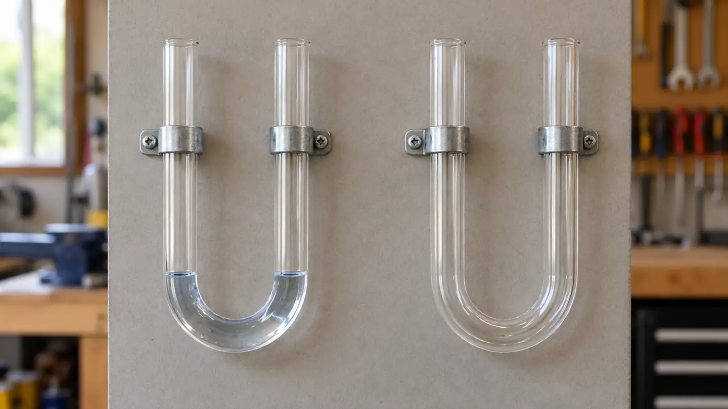
Place taps where they represent the intended pressure difference and can be inspected. A tap in a stagnant pocket may see accumulated solids; one near strong turbulence or a bend may not represent the pressure assumed by a flow-element calculation. Protect lines from mechanical damage and route them so that inspection and maintenance are practical. Follow the applicable primary-element and transmitter manuals for tap orientation, manifold design and commissioning.
Do not open or equalize process connections based on a generic online checklist. Pressurized, hot, toxic or flammable systems require site-specific isolation and operating procedures. A visual review of a trend does not establish that an impulse line is safe to service.
Choose materials, mounting and electrical output together
For liquid or gas process service, confirm compatibility of diaphragms, seals, fittings and any fill fluid with the actual medium, cleaning chemicals and temperature. If a diaphragm seal is required, its capillary and fill-fluid temperature behavior become part of the measurement chain. An installation with aggressive cleaning cycles can differ from a nominal room-temperature datasheet condition.
Mount the instrument according to its manual. A change in orientation or a mechanically stressed connection may affect zero for some low-range devices. An enclosure rating does not automatically establish chemical compatibility or suitability for every washdown method. Consider vibration, condensation, sunlight, accessibility and the environment around electrical connectors.
Analog outputs such as 4–20 mA or voltage signals and digital outputs each require a matching controller input. Verify the supply, wiring, load limits, signal range, units and fault state. With a 4–20 mA output, determine whether the controller interprets the lower and upper values as the intended engineering range and whether an out-of-range current indicates a measurement or fault condition. The specific behavior belongs to the transmitter and controller manuals.
Compare a filter application with a room-pressure application
In a filter application, the required pressure points lie on opposite sides of an element. The useful signal is the loss across that element at an identified operating flow. Before choosing a range, collect expected clean and maintenance-condition values from the filter or system documentation, then consider startup and abnormal-flow conditions. A sensor mounted on a bypass with both lines routed to the same side of the filter can show a credible number that answers the wrong question. A process sketch with clearly identified taps is therefore part of the specification.
In a room-pressure application, a small change around zero can reverse the inferred pressure direction. Doors, reference-space pressure and ventilation operating modes may affect the reading. Bidirectional range, low-end offset and stability may matter more than a large maximum span. Determine whether the decision is based on a brief indication, a sustained trend or an alarm; then evaluate the sensor and control system at the relevant timescale. Do not infer a particular room's compliance from a generic differential-pressure threshold.
These examples also show why a signal's physical meaning should be recorded with its units. “Pressure 20 Pa” is incomplete without two locations and a sign convention. Across a filter it describes a loss; between rooms it describes their relative pressure. If either tap is moved, label the resulting series so that the apparent step is not mistaken for a process change.
Scaling and sign: an illustrative calculation
Suppose a transmitter is configured for −100 to +100 Pa and produces 4–20 mA linearly across that range. Under that stated configuration, 4 mA corresponds to −100 Pa, 12 mA to 0 Pa and 20 mA to +100 Pa. If a controller mistakenly assumes a 0 to 200 Pa scale, the same 12 mA signal will display 100 Pa rather than zero. The instrument and control system may each be functioning correctly, yet the combined indication is wrong.
This example does not prescribe an output configuration for every model. Some devices offer other scales or fault-current behavior. During commissioning, record the configured lower and upper range values, units and output convention at both ends of the signal path. Confirm at several suitable test points, including zero and the region where a decision is made. A wiring or scaling check is separate from a pressure-path check: either can pass while the other remains wrong.
Commissioning and verification

Commissioning should establish the instrument configuration and the installed measurement path. Record the model, serial number, port assignments, selected range, output scaling, mounting position, medium and relevant pressure and temperature conditions. Confirm that both pressure paths are connected to their intended taps and that the controller's engineering units match the transmitter configuration.
Verification uses a suitable reference to compare the output at specified points, including the working region and zero when appropriate. Check the reference instrument's range and uncertainty; it should be suitable for the tolerance being evaluated. A laboratory comparison at atmospheric pressure is useful but may not capture field effects from common pressure, impulse lines and process temperature. Record the conditions so the result is not mistaken for a complete installed-system validation.
Check the reference and document the result
Choose a reference that covers the test range and has uncertainty appropriate to the acceptance tolerance. A reference instrument with a wide range may be insufficiently precise at a very small differential even if it can display the value. Calibration records should identify the reference, its status, the applied points and the environment. For an analog output, record both the actual electrical signal and the controller's displayed engineering value when the purpose is to validate the entire chain.
Where safe and technically appropriate, compare increasing and decreasing test points to reveal hysteresis or a stuck mechanism. Allow the instrument and reference to stabilize as their procedures require. A rapid check may show whether the system responds but cannot by itself establish long-term stability or its complete uncertainty over temperature and static pressure. Report what was actually checked and avoid extending the conclusion beyond the test conditions.
An as-found result is valuable even if the instrument later passes after adjustment. It shows whether earlier data might have been affected and whether the verification interval is appropriate. Preserve the original configuration, the reason for adjustment and the as-left check. If a pressure line was cleaned or replaced at the same time, record that intervention separately: a better reading may be due to the restored pressure path rather than an electronic calibration change.
| Symptom | Possible causes to investigate | Evidence that helps |
|---|---|---|
| Negative value where positive was expected | Reversed ports, actual flow reversal or sign/scaling configuration. | Tap labels, process direction and transmitter configuration. |
| Flat value despite process change | Blocked line, closed isolation, saturation, frozen output or real process stability. | Status flags, signal checks and qualified inspection of the pressure paths. |
| Slow response | Long or partially blocked line, damping, trapped gas or process behavior. | Response comparison and line condition under approved procedures. |
| Shift after maintenance | Mounting change, line fill, temperature, zero or configuration change. | As-found/as-left records and documented installation conditions. |
| Noisy signal | Pulsation, vibration, electrical interference or unsuitable damping. | Raw signal, process operating state and wiring inspection. |
Troubleshoot the complete chain before replacing or recalibrating the transmitter. The ICS Schneider discussion illustrates why incorrect pressure paths and zero conditions can resemble a defective sensor. Its examples are diagnostic prompts, not a substitute for the procedures and limits of your installation.
A procurement worksheet
Before requesting a quotation, state the medium and purpose; mark the H and L taps on a process sketch; specify the minimum, normal and maximum differential; list normal and maximum static pressure at each port; and describe credible one-sided pressure events. Include the working temperature, cleaning chemicals, materials, electrical output and required response time.
Next, define the required uncertainty at the decision point rather than asking only for a high accuracy percentage. Include expected ambient and process conditions, calibration interval and reference availability. Ask the supplier to identify which specifications apply to the exact part number and which conditions are excluded. Finally, record who will install, inspect and verify the pressure paths over the sensor's working life.
Preserve context in the long-term record
Store the two tap locations, sensor orientation, range and units with the signal tag. Include the active configuration and a dated note when the instrument, primary element, pressure lines or controller scaling changes. A trend that shifts after a maintenance event is easier to interpret when the record shows whether a line was cleaned, a transmitter was re-ranged or a filter was replaced.
For filter monitoring, record the flow or operating mode alongside differential pressure. Comparing a reading at low flow with one at high flow can exaggerate or conceal the effect of filter loading. For a room, record ventilation mode and relevant door events where practical. For a flow element, retain the calculation configuration and the fluid-property basis. These supporting variables let an operator distinguish a change in the process from a change in the conditions under which the pressure was measured.
For a broader HVAC context, the guide to interpreting HVAC pressure readings discusses how air, refrigerant and hydronic pressure readings answer different questions.
Часто задаваемые вопросы
Is differential pressure the same as gauge pressure?
No. Differential pressure compares two defined pressure points. Gauge pressure compares a pressure with local atmospheric pressure. A device may measure a difference relative to atmosphere, but its configuration and reference must be stated.
Can I subtract two independent pressure sensors?
Sometimes, if their ranges, references, timing and combined uncertainty suit the task. When the desired difference is small relative to each sensor's range, offsets and drift can dominate the subtraction. Evaluate the entire measurement uncertainty before assuming two general pressure sensors are adequate.
Why can a small differential require a high-pressure-rated transmitter?
Both ports can sit at high common pressure while their difference is small. The differential span describes the measured difference; the working and overload ratings describe pressure resistance under defined conditions.
Does a higher filter differential always mean the filter is clogged?
No. A filter's pressure drop also depends on flow and other operating conditions. Compare similar states and follow the filter manufacturer's criteria.
Does zero adjustment fix a blocked impulse line?
No. Zero adjustment cannot restore a representative process pressure to a blocked or leaking path. Inspect and verify the measurement chain using the applicable site procedure before changing calibration.
How often should a differential pressure transmitter be checked?
Use the manufacturer's instructions, site requirements, process risk and observed stability to establish an interval. Maintain verification records and revise the schedule when evidence supports it.








оставьте ответ