
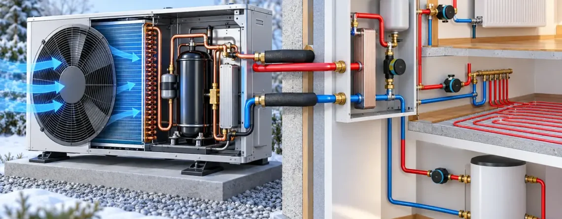
A useful heat-pump sensor suite depends on the question it must answer. Built-in temperature and pressure sensors may control and protect the refrigeration cycle; a matched flow-and-temperature heat meter measures heat delivered to a water circuit; an electricity meter measures input energy; temporary probes and airflow instruments support commissioning; and a refrigerant detector addresses a separate leak-safety task where the appliance design requires one. No single “heat pump sensor” or pair of pipe temperatures can prove efficiency, correct refrigerant charge and refrigerant safety at once.
Choose the measurement boundary before choosing hardware. An air-to-water heat pump with a hydronic distribution loop allows a different heat-meter arrangement from an air-to-air ducted unit. A ground-source machine has another source circuit. A monitor that sees only the compressor's electricity is not measuring the same input as one that includes pumps, fans and backup heat. The SEAI heat-pump operation guide explicitly ties efficiency interpretation to the chosen system boundary.
Four decisions before making a sensor list
The first task is equipment control and protection. The heat-pump controller uses temperature, pressure, flow or switch states to start, stop, regulate and protect components. These inputs belong to the appliance design. They are not necessarily calibrated as independent billing-grade or performance meters. The second task is performance accounting: how much useful heat reached a defined boundary, and how much electricity crossed that same boundary over a defined time. That typically requires dedicated heat and electric metering.
The third task is diagnosis and commissioning. A technician may temporarily measure refrigerant pressures, pipe temperatures, duct static pressure, airflow, electrical power and operating state to test a suspected problem against manufacturer guidance. A permanent dashboard may expose some of those points, but temporary calibrated instruments may still be necessary. The fourth task is refrigerant leak safety, which is separate from efficiency. If the equipment and applicable rules require an integral refrigerant detection system, its alarm and mitigation chain must be evaluated for that purpose. A compressor pressure trace is not an ambient gas detector.
| Decision | Core observations | Can answer | Cannot establish alone |
|---|---|---|---|
| Control/protection | OEM temperatures, pressures, flow switches, state signals | Whether the controller sees conditions used by its algorithms | Delivered heat, independently measured COP or room-gas safety |
| Heat and energy | Hydronic heat meter and correctly scoped electric meter | Heat output, energy input and defined-period performance | Exact cause of a fault without operating context |
| Diagnosis | Service probes, airflow/static-pressure tests, electrical checks | Whether a particular operating condition matches OEM expectations | Universal repair conclusion from one number |
| Refrigerant safety | Suitable detector, controller, fault and mitigation chain | Whether an abnormal gas condition triggers the designed response at monitored points | Refrigerant charge or seasonal efficiency |
The distinction prevents an expensive monitoring project from collecting dozens of values with no decisions attached. For each proposed sensor, write a sentence beginning “We will use this signal to…” and name the action or calculation. If no action or inference survives that test, postpone the sensor until the measurement purpose is clearer.
Map the actual heat pump before placing instruments
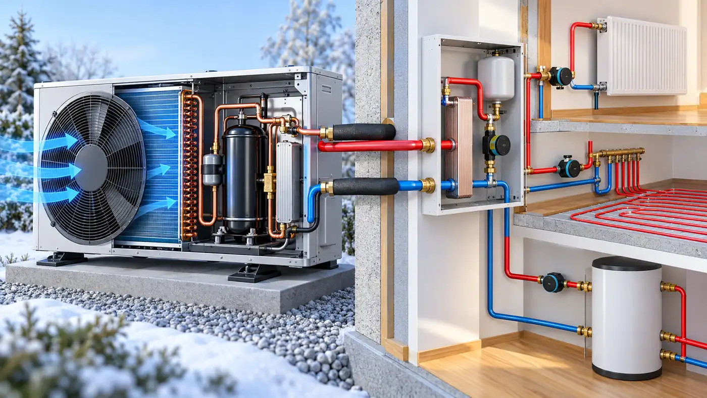
Start with the system schematic. In an air-to-water system, outdoor air exchanges heat with the refrigerant circuit, while a water or water-glycol circuit carries heat to emitters or a hot-water tank. For performance metering, the hydronic flow and return pipes are often accessible points. In an air-to-air system, delivered heat is transferred through an air stream, so airflow and supply/return air conditions become relevant; a water-side heat meter has no place. A ground-source heat pump adds source-loop inlet and outlet temperatures and sometimes source-loop flow to the picture. OpenEnergyMonitor's tiered heat-pump monitoring guide shows how monitoring expands from electricity and temperatures to actual heat metering depending on the installation.
Define which heat output is “useful.” Is it heat leaving the heat-pump unit, heat entering a buffer tank, or heat delivered beyond distribution losses to emitters? If domestic hot water is produced, is it included with space heating or measured separately? If a backup electric heater sits downstream of the primary heat meter, its output may be counted while its electricity is excluded unless the input boundary is deliberately defined. The answer changes the interpretation of any calculated COP or seasonal performance factor. SEAI's guide cautions that pumps, fans and integrated heaters may be included or excluded in different efficiency boundaries.
Also determine which signals already exist inside the appliance and whether they can be read reliably. Stiebel Eltron's heat-pump manager commissioning documentation illustrates the breadth of controller points that one product family can expose: flow and return temperature, source and coil temperatures, refrigerant-side temperatures, multiple pressures, water flow and electrical states. That list is a product example, not a universal minimum. A manufacturer may filter or calculate a displayed value, and its update rate or uncertainty may differ from a calibrated external meter.
Measuring delivered heat in a hydronic system
A hydronic heat meter commonly combines a flow sensor, a matched pair of supply and return temperature sensors, and an integrator that uses the heat-transfer fluid properties to calculate energy. In simplified form, instantaneous thermal power is proportional to mass flow multiplied by specific heat capacity and the temperature difference. The actual calculator accounts for the meter's fluid and measurement method. Measuring only two temperatures does 不是 determine heat output; the flow rate is also needed. Measuring flow without a trustworthy temperature difference is similarly incomplete.
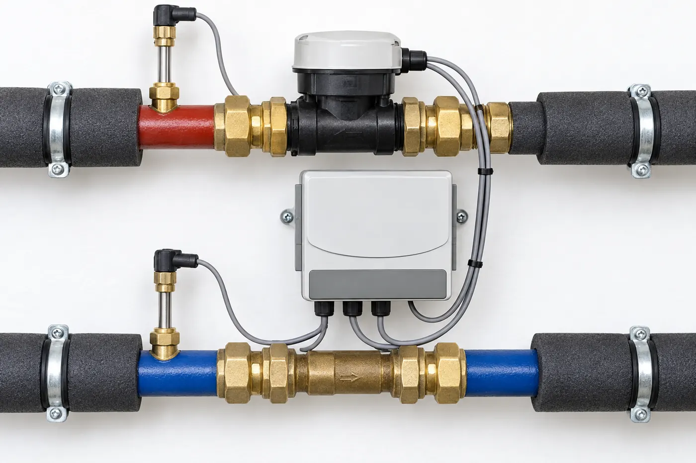
這 SEAI Heat Pumps Technology Guide describes flow technologies, matched temperature probes and the calculator. It also explains that installation and fluid composition matter. A water-glycol mixture does not have the same thermal properties as plain water; some heat meters are calibrated or configured for a specified mixture. If glycol concentration changes, the heat calculation may change. That is a metering issue, not merely a freeze-protection issue.
Place the temperature sensors so they truly bracket the heat flow being claimed. A probe in a nearby mixed header may not represent the heat-pump outlet. A poorly seated sensor in a thermal pocket can lag or read an intermediate temperature. Matched probes matter particularly when the supply-return difference is small: a small relative offset between them can become a large fraction of the measured difference. The SEAI guide discusses matched pairs, thermal pockets, lead integrity, flow direction and meter-specific straight-run and installation requirements. Follow the chosen meter's instructions rather than borrowing a pipe-length rule from another model.
The flow sensor must suit the pipe diameter, flow range, fluid, temperature, orientation and installation space. An ultrasonic transit-time meter, a vortex or fluidic device and a mechanical meter have different sensitivities to air bubbles, turbulence or orientation. Select according to the meter's stated installation conditions and the expected minimum and maximum flows. A meter that reads accurately at design flow but poorly during part-load operation can distort long-term heat totals. Record the actual meter location and calibration/configuration so that later trends can be interpreted.
The temperature difference deserves particular attention when an operator compares two meters. If the true supply-return difference is small, even a modest mismatch between probes can create a large relative error in the calculated heat rate. A common sensor accuracy figure applied separately to two probes does not state the accuracy of their 不同之處. Matched-pair calibration, correct immersion and thermal contact are therefore more meaningful than choosing two individually impressive but unmatched probes. The heat meter's complete uncertainty statement should be used for any formal energy claim. This is one reason a controller's trend sensors can be excellent for control yet inadequate as an independently verified heat meter.
For an air-to-air heat pump, equivalent delivered-heat measurement is more complicated because heat capacity depends on airflow and air enthalpy, including humidity in some conditions. Duct temperature split alone is not a heat meter. A field technician may use airflow measurement and psychrometric observations for commissioning or diagnosis, but an assumed fan flow and two temperature probes do not automatically provide defensible seasonal heat output. The instrumentation plan should match the system type and desired accuracy.
Measuring electricity across the same boundary
The denominator of a performance ratio must be as carefully defined as the numerator. Decide whether the meter covers just the outdoor unit, the indoor unit, source and circulation pumps, distribution fan, controls, standby draw, backup heater, defrost energy and domestic hot-water equipment. There is no single correct boundary for every comparison, but there must be a declared one. A whole-house smart-meter figure includes unrelated loads; a compressor current clamp may omit important heat-pump auxiliaries. Neither should be called “heat-pump electricity” without qualification.
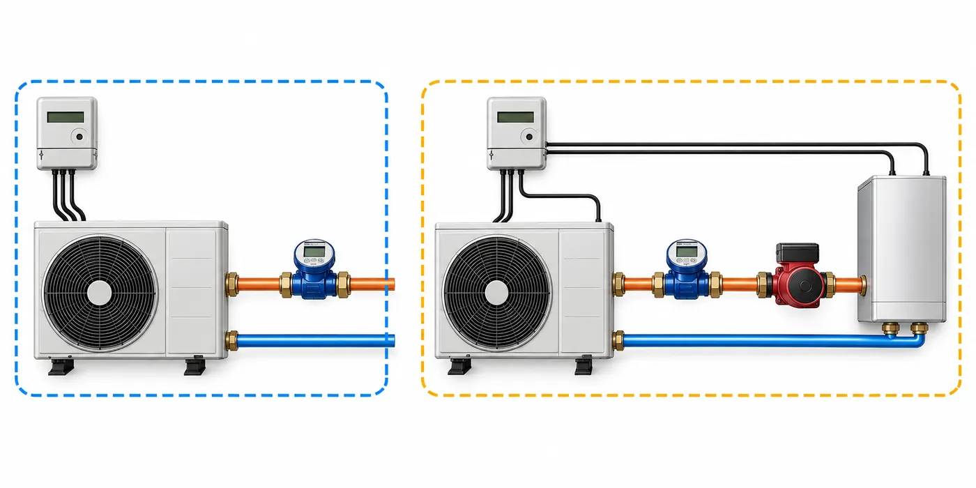
An electric meter should capture true energy over the same period as the heat meter. Instantaneous current is not equal to electrical power unless voltage, power factor and measurement method are also handled. A controller's estimated power display may be useful for trends but should not be assumed equivalent to an independent metering-grade energy register. SEAI's operation guide recommends explicit electricity metering and explains that the meter points depend on system configuration and the SPF boundary.
Backup heat deserves its own channel where possible. If an immersion heater silently runs during cold weather or high-temperature hot-water production, a system that measures only compressor input can appear surprisingly efficient or inefficient depending on how output is counted. Separate metering and logged operating state make the cause visible. The same principle applies to source pumps and distribution fans: whether they are included in the reported performance must be stated. Time alignment matters too. Comparing today's heat total with yesterday's electricity or mixing intervals across a daylight-saving change creates an artificial efficiency value.
Use a defined reporting interval. Instantaneous COP can vary widely during starts, defrost and transitions, so a brief snapshot is not a seasonal result. SEAI describes seasonal performance factor as heat output divided by electricity input over a meaningful period, with the boundary specified. For an operator, a weekly or monthly trend can reveal changes, but comparisons should account for weather, load and operating mode. A lower value during domestic-hot-water production or a cold, humid week is not automatically a sensor fault.
Airside and source measurements explain changing load
Outdoor-air temperature is essential context for an air-source heat pump. Coil or evaporator temperature and humidity conditions can help explain frosting and defrost events. Supply and return water temperatures show the lift demanded by the building; room or thermostat temperatures show whether that heat is meeting comfort needs. None of these single points is a complete efficiency measurement, but together they explain why electricity and heat output changed.
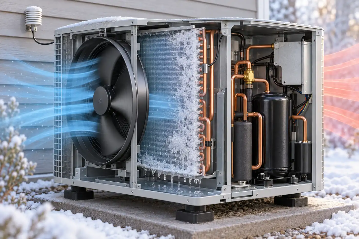
Airflow matters for both air-to-air systems and air-source equipment. On a ducted system, a restricted filter, closed register or duct problem can change coil conditions and delivered heat. PNNL's heat-pump commissioning guide discusses total external static pressure, direct or inferred airflow measurement and duct leakage tests for applicable ducted installations. It also separates the procedures needed for ducted and ductless equipment. A duct static-pressure number must be compared with the particular blower performance and installation, not a universal good/bad threshold.
Source-side monitoring differs for ground-source or water-source systems. Entering and leaving source-fluid temperatures, source flow and pump state can indicate whether the heat source is delivering expected conditions. A control sensor may protect against freezing, while a separate energy study may need more accurate metering. Avoid a generic “outside temperature” channel on a ground-source system when the actual source is a buried loop or water circuit. The physical source dictates the instrumentation.
Use operating state as a first-class data channel. Record heating versus cooling, compressor speed or stage, pump/fan command, defrost, backup heat, setpoints and alarms where the equipment exposes them. Without state, two identical temperature values may represent a healthy steady period in one interval and a transition in another. Good sensor placement cannot rescue interpretation when mode changes are invisible.
Refrigerant-side sensors are for qualified diagnosis and control
Heat pumps also contain a refrigerant cycle. Pressure transducers, pipe thermistors and protective switches may support expansion control, compressor protection and defrost logic. During commissioning or troubleshooting, qualified personnel may use calibrated pressure instruments and clamp-on temperature probes to compare observed conditions with the manufacturer's expected values. PNNL's commissioning guide includes refrigerant charge verification and controls checks among core procedures; the detailed method depends on the equipment and refrigerant.
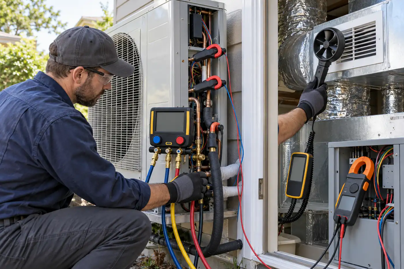
A displayed low-side pressure is not a direct “charge remaining” gauge. Airflow, water flow, outdoor conditions, compressor modulation, valve behavior and mode all affect pressures and temperatures. Superheat or subcooling observations require the right measurement points and system type; their target values are manufacturer and condition specific. A trend that appears to suggest undercharge may instead reflect a faulty pressure transducer, misplaced temperature probe, flow problem or control transition. Separate a sensor plausibility check from a refrigerant diagnosis.
Permanent process sensors and temporary service instruments can have different purposes and accuracy classes. A control thermistor optimized for repeatable regulation might be sufficient for the OEM algorithm but not for an independent heat-energy calculation. A technician's manifold may read the service port but not the exact point in the controller's hydraulic or refrigerant model. Record the measurement point and uncertainty whenever unlike instruments are compared. Bosch's technical troubleshooting example illustrates how the location and plausibility of a specific coil temperature sensor matter before a fault conclusion is drawn; its model-specific test values should not be applied to unrelated heat pumps.
Safety devices and alarms are a separate layer. If a heat pump uses a refrigerant and appliance configuration for which an integral detection system is required, the detector, controller and mitigation sequence need their own documentation. See our guide to the different jobs of refrigerant sensors for the distinction between ambient detection, portable leak search and process measurement. A product-specific A2L refrigerant sensor module illustrates why gas type, output and installed controller must be read together; it is not a universal add-on for any heat pump.
Make the data trustworthy before adding more sensors
The most common monitoring errors are mundane: a sensor is in the wrong pipe, a probe is uninsulated, a flow meter faces the wrong direction, a controller channel uses the wrong unit, or timestamps drift. Use a commissioning register that contains each point's location, serial number where applicable, engineering units, calibration/configuration, update interval, expected state and owner. Photograph or sketch locations in project records; do not rely on a dashboard label such as “T2” that future operators cannot decode.
Check plausible values before calculating performance. Are supply and return reversed during heating? Does reported flow become nonzero when the pump is off? Does a temperature probe track a nearby independent instrument after stabilization? Does electric energy advance during a known backup-heater event? Do fault flags change with a disconnected sensor in the manufacturer's approved test? These checks should follow equipment procedures and avoid altering safety controls. They establish that the measurement chain works, not that the heat pump is efficient.
Sampling frequency should match the question. Slow cumulative energy registers can support monthly performance, while short start-stop cycles and defrost need finer time resolution and synchronized state channels. Higher frequency is not automatically better if measurements are noisy or the storage system drops data. For comparative analysis, retain raw meter totals as well as calculated rates so that gaps and counter resets can be identified. If the meter's volume-flow reading is combined with a temperature difference from another logger, align their clocks and fluid assumptions.
A useful point schedule can be short:
| Use case | Minimum useful data | Add only when the question requires it |
|---|---|---|
| Basic operation | Outdoor/source condition, flow/return temperature where present, operating mode and alarm log | More thermal points for component-level diagnosis |
| Hydronic performance | Calibrated heat meter plus correctly scoped electricity meter and backup-heat state | Separate circuits or source-side meters for boundary analysis |
| Ducted comfort/commissioning | Supply/return air conditions, airflow or static-pressure test, control state | Permanent zone sensors if an ongoing comfort problem warrants them |
| Refrigerant diagnosis | OEM process trends plus qualified temporary service measurements | More permanent process sensors only if the design supports them |
| Refrigerant safety | The specified detector and response chain for the actual appliance/refrigerant | Additional coverage only after a site-specific assessment |
The order matters. Start with a clear problem, then choose the few measurements that could distinguish competing explanations. If a comfort complaint occurs only after defrost, log state and supply conditions before buying a pressure sensor. If seasonal energy use is the problem, establish heat and electric boundaries before interpreting compressor temperatures. If there is a refrigerant alarm, use the prescribed safety response before pursuing efficiency analysis.
Conditional examples of useful trend interpretation
Imagine a hydronic heat pump whose flow temperature rises while return temperature barely changes and the flow meter reports a lower rate than usual. The heat meter's delivered-power trend may fall even as the compressor runs. Possible explanations include changed hydraulic flow, a valve state, air in the circuit, meter error or a control response; the pattern is not enough to identify one fault. Check pump/valve commands, filter condition and sensor plausibility against the OEM procedure. In contrast, a report of high supply temperature with no flow measurement cannot quantify delivered heat.
In another scenario, electricity rises on cold days while delivered heat remains steady and defrost events become more frequent. That could reflect expected source conditions, excessive cycling, airflow restriction or another cause. Compare similar weather and load periods, inspect operating state and airflow context, then involve qualified service if the behavior deviates from the equipment's expected operation. Calling the heat pump “inefficient” from a single cold-day ratio discards the time and boundary conditions that give the number meaning.
Finally, suppose a controller shows normal supply and return temperatures but occupants report insufficient room heat. The plant may deliver heat to a buffer tank while a distribution valve is closed or a circulator is off. A heat meter placed on the unit outlet and one beyond the distribution boundary would answer different questions. Rather than multiplying sensors everywhere, trace where the heat should cross each boundary and meter the one relevant to the complaint.
These are reasoning examples, not field test results. Their value is the method: pair a trend with location, time, operating state and a rival explanation before diagnosing a component.
Questions readers often ask
Can two pipe temperature sensors calculate COP?
No. Water-side heat output requires flow rate and fluid properties as well as a trustworthy temperature difference. COP also requires electricity input over the same period and a declared system boundary. Two temperatures can be valuable for control or diagnosis without constituting a heat meter.
Are built-in controller sensors accurate enough for performance monitoring?
Sometimes they are useful for trends, but the answer depends on the OEM's stated accuracy, location, update method and whether the values are calculated or measured. Independent heat and electricity meters are preferable when the result must support a defensible energy comparison or contractual claim.
Which pressure sensor is most important?
There is no universal extra pressure sensor. The OEM provides the process sensors its control and protection system needs. For a diagnosis, qualified personnel identify the relevant refrigerant or hydraulic pressure point from the fault question and service instructions. An added sensor should have a defined purpose and appropriate range, connection and compatibility.
Should every heat pump have a refrigerant gas detector?
No blanket answer follows from the term “heat pump.” Requirements depend on refrigerant, charge, equipment type, listing, installation and applicable rules. Where a detection system is part of the appliance design, follow its specified parts and instructions; a generic room monitor or aftermarket module cannot be assumed to replace it.
What is the most useful first upgrade to a basic dashboard?
If the aim is efficiency, define the heat and electricity boundaries and determine whether a suitable heat meter and electric meter exist. If the aim is fault diagnosis, add the missing operating state or point that distinguishes plausible causes. The best first sensor is the one that answers a specific unresolved question.
Good heat-pump monitoring is a map of decisions rather than a pile of readings. The water or air stream tells you what heat crossed a boundary; electricity tells you what the system consumed; process and state points explain how it operated; and refrigerant safety is handled by its dedicated response chain. With each channel named honestly and installed correctly, a modest suite is more informative than a dashboard full of ambiguous numbers.









發表評論