
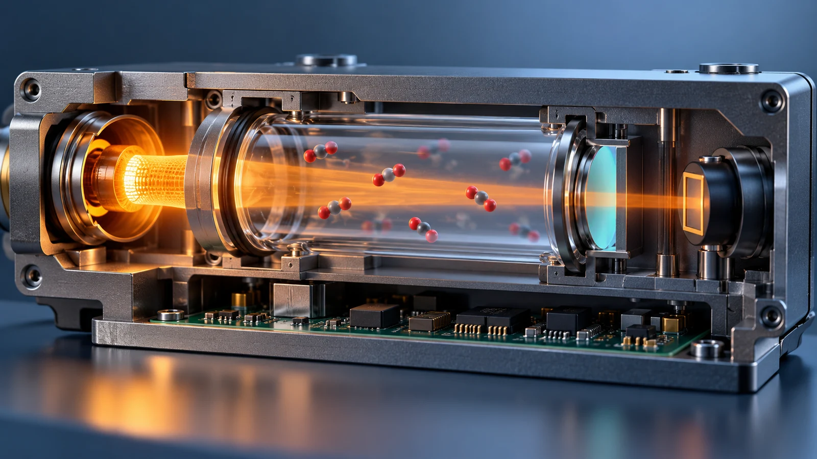
An NDIR CO₂ sensor does not count individual molecules. It estimates concentration from the infrared light that reaches a detector after passing through a gas sample. The useful question is therefore not just whether a module is “NDIR,” but which gas reaches its optical cell, which wavelengths are measured, and how the optical signal becomes a reported value。
The chain is straightforward in principle: an infrared source illuminates a gas path; CO₂ absorbs part of the light in a selected band; a detector measures the remaining signal; electronics use calibration and appropriate compensation to report concentration. The design details determine what the resulting number means and where it can be trusted.
What Does NDIR Actually Measure?
Non-dispersive infrared (NDIR) describes a way of selecting an infrared band without dispersing the light into a full spectrum. CO₂ has an absorption band around 4.26 µm, so a CO₂ channel can compare transmitted light in a suitable band with a reference or calibrated baseline. A different target gas requires an appropriate optical band and its own calibration; software cannot turn any NDIR module into a universal gas detector.
In a simplified, monochromatic model, transmission follows T = I/I₀ = e^(−εcL), 在哪里 我 is transmitted intensity, I₀ is incident or reference intensity, ε represents absorption under the defined conditions, c 是浓度并且 l is optical interaction length. This relationship explains why increasing concentration or path length increases absorption. A real module uses a finite filter band, a source spectrum, detector response and a fitted calibration curve; the equation is a design guide, not a drop-in conversion formula for an arbitrary voltage. Hamamatsu's NDIR design explanation presents the optical principle and example configurations.
NDIR measures an optical response to gas in the cell. The final display may use ppm or percent, depending on the application and specified range. For the reporting units, see CO₂ ppm, percent conversion and sensor ranges。
Follow the Complete Optical and Electronic Chain
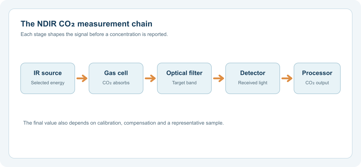
| Stage | Job | A practical question |
|---|---|---|
| Gas entry and cell | Admit the gas being measured and define its interaction with light | Does the sample represent the room, duct or process point? |
| Infrared source | Provide usable energy in the selected band | How does the design detect source change over time? |
| Optical path and filter | Define interaction length and reject unwanted wavelengths | What gas and concentration interval is this optical design calibrated for? |
| Detector and electronics | Convert received infrared energy into a stable signal | Is there enough signal over the full operating range? |
| Reference and calibration | Separate useful absorption from characterized drift and map it to concentration | What is corrected by design, and what needs a known reference? |
| Environmental inputs and output | Apply model-specific corrections and report data | Are pressure, temperature, humidity and validity status handled as specified? |
These stages are connected. A capable detector cannot fix a sample that never reaches the cell. A stable source does not by itself correct a pressure setting that does not match the installation. An accurate sensor component also cannot prove the performance of an assembled monitor without considering enclosure, airflow, display, alarm and maintenance.
1. Getting the Right Gas into the Cell
Diffusion modules rely on surrounding air reaching the sensing area. Pumped and flow-through arrangements bring a defined stream to an analyzer. Position, enclosure openings, filters, tubing and flow can affect which gas is actually measured and the time required for a change to appear. For a room monitor near an occupant, the sample may differ from that at a return-air duct or the outdoor-air intake. For a process line, moisture and pressure may matter before the optical measurement begins.
The sampling arrangement is therefore part of the measurement chain, even when the data sheet is headed “CO₂ sensor.” Define the sample location and any preconditioning before comparing modules.
2. Source, Filter and Detector
The source must deliver infrared energy that overlaps the target band's absorption. The cell guides that energy through the gas. A filter or wavelength-selective system gives the detector a band useful for CO₂ rather than treating all received infrared energy as equivalent. Some designs use a second wavelength or reference channel. Other designs rely on different stabilization and calibration methods. The term “dual channel” alone does not tell you precisely how two signals are acquired.
The detector measures received energy, not concentration directly. Electronic processing must account for background, source modulation, amplification, noise and the module's optical geometry. At high absorption the transmitted signal can become small; at low absorption the change from baseline can be close to noise and drift. A good design is matched to its intended range rather than assumed to be equally useful from outdoor background to a concentrated process sample.
3. Reference, Calibration and Compensation
The reference signal helps distinguish target-gas absorption from some changes in the optical system. Its benefit depends on the implementation. For example, Sensirion describes the SCD30 作为双通道透射式 NDIR 模块,其中参考通道支持长期稳定性。 Vaisala's CARBOCAP explanation 描述了一种不同的布置:沿着相同的光路测量吸收和非吸收参考波长。这些是真实的设计示例,并不是假设每个参考通道都能纠正每种污染的理由。
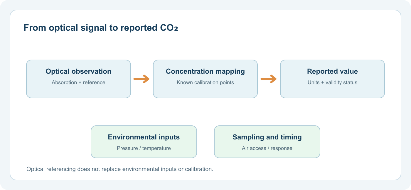
校准建立了特定条件下信号与已知 CO2 浓度之间的关系。参考渠道并不能取代这种关系。它也不会自动纠正错误的样品压力、加热的外壳或安装无法满足的校准假设。我们检查这些限制 NDIR 参考通道可以补偿什么。
Why the Reported Value Can Differ from the Gas Fraction
The optical signal responds to the number of absorbing molecules along the path. If temperature or pressure changes, the number density in the cell can change even when the gas mixture's fraction is unchanged. Whether and how a module corrects this depends on its design and configuration. Sensirion's SCD30 interface description provides pressure and altitude compensation inputs for that particular module. Its design-in guidance explains how airflow-induced pressure changes and nearby heat sources can affect installation performance.
Humidity deserves similar care. Some modules integrate relative-humidity and temperature sensing and use those inputs in characterized algorithms. This does not mean water vapor has been universally “removed” from all measurements, or that a display always reports the same dry-gas basis as a laboratory reference. Ask for the manufacturer's reporting basis and specified environmental range when comparing methods.
时间也很重要。源预热、电池中的气体交换、固件平均和显示更新都会影响观察到的响应。短传感器响应规格不一定是限制性外壳或长管后面的成品监视器的响应。
如何阅读 NDIR CO2 规格
开始于 测量范围, 精度范围, 测试条件 和 校准行为 as separate fields. A digital output may represent values outside the interval for which accuracy is specified. The manufacturer's claim should identify the concentration interval and operating environment in which it applies.
这 SCD30 数据表 说明了这种区别:其接口输出范围和校准精度范围并不相同。规定的精度与 400–10,000 ppm 间隔和记录条件相关。其自动自校准还依赖于传感器暴露在适当的低二氧化碳参考环境中。这些是 SCD30 特定的事实,而不是一般 NDIR 的规范。
对于任何候选模块或成品设备,请询问:
- Which gas is the filter and calibration intended to measure, and how is cross-sensitivity handled?
- What are the specified accuracy and repeatability intervals, not just the possible display range?
- Which pressure, temperature and humidity inputs are measured or supplied externally?
- What are the calibration, baseline and drift requirements for the actual duty cycle?
- How do air access, tubing, enclosure and data processing affect the assembled device?
Our broader 二氧化碳测量指南 helps translate these into an instrument selection brief. For a deeper sensor-technology overview, Gasnose's NDIR guide compares optical choices and their limits.
Typical Misreadings of the Technology
“NDIR means a complete CO₂ safety instrument.” NDIR names the sensing principle. A safety application requires a complete device and a documented intended use, including sampling, alarms, installation and applicable requirements.
“A reference channel eliminates calibration.” It can reduce certain optical drifts. It cannot establish concentration from an uncalibrated optical response or repair every form of contamination.
“A longer path is always more accurate.” Longer interaction can increase low-concentration absorption, but high-concentration transmission may become too small and optical losses may reduce signal-to-noise ratio. The usable range is a system property. See optical path length and CO₂ sensor design。
“All gas molecules can be measured by the same IR channel.” A channel is designed for gases with relevant absorption in its selected band. Oxygen and nitrogen, for example, are not measured by an ordinary CO₂ NDIR channel. Carbon monoxide measurement also should not be inferred from a CO₂ sensor's presence; its wavelength selection, calibration and instrument documentation must be specific to CO.
A Working Definition
An NDIR CO₂ result is a calibrated estimate from a defined optical and sampling system. The source, gas path, spectral selection and detector produce a signal; referencing, environmental inputs and calibration turn that signal into a concentration value within stated conditions. Reading the entire chain is the reliable way to compare sensor modules and finished instruments.
常见问题
Does an NDIR sensor measure CO₂ directly? It directly measures an optical absorption response attributable to CO₂ in its designed band, then estimates concentration using calibration. It does not count molecules one by one.
Is every dual-channel sensor more accurate than every single-channel sensor? No. Channel architecture can improve stability, but accuracy also depends on optics, calibration, conditions and integration. Compare documented instrument performance.
Can a CO₂ NDIR module measure methane or refrigerants? Not merely by changing software. Those applications require a suitable optical band, calibration and complete instrument design for the target gas.
Why can two CO₂ monitors disagree? They may sample different air, use different averaging or compensation settings, or operate outside their specified conditions. Compare them at the same location and under a controlled procedure before attributing the difference to sensor drift.

How to Build a School IAQ Monitoring Record That Leads to Action
Use linked room, occupied-event and issue logs to turn school CO2 observations into reliable ventilation follow-up.
阅读更多
Where to Place CO2 Monitors in School Classrooms
Choose representative school classroom CO2 monitor positions by occupancy and air paths, then verify, document and maintain the installation.
阅读更多
How to Interpret Classroom CO2 Readings for Ventilation
Interpret classroom CO2 readings as occupied ventilation clues with context, local guidance, monitor checks and repeatable follow-up.
阅读更多



评论 (2)
[…] optical path length, detector and calibration are designed together for the target range. See our NDIR measurement-chain guide and optical path-length explanation for the underlying […]
[…] conditions. The existence of a digital CO₂ output does not imply an independent CO result. Our NDIR measurement-chain guide explains what the optical path, detector and calibration […]