
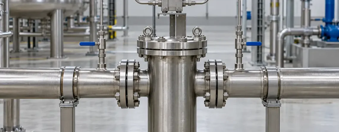
Wählen Sie einen Differenzdrucksensor aus, indem Sie ihn definieren die beiden Druckpunkte, der nutzbare Differenzbereich und der maximale Druck, dem jeder Anschluss ausgesetzt sein kann. Überprüfen Sie anschließend die Genauigkeit am Arbeitspunkt, die Medienverträglichkeit, die Druckabgriffe, die Impulsleitungen und die Art und Weise, wie das Signal überprüft wird. Ein Gerät, das für einige Pascal an einem Luftfilter geeignet ist, kann für einen kleinen Druckabfall in einer Hochdruckflüssigkeitsleitung ungeeignet sein, selbst wenn beide Messwerte als Differenzdruck bezeichnet werden.
Der Differenzdruck ist eine Differenz zwischen zwei Drücken und kein direktes Maß für Filterreinheit, Durchfluss oder Flüssigkeitsstand. Ein zuverlässiges System muss einen repräsentativen Druck von jedem Punkt zum Sensor bringen und seinen Ausgang korrekt skalieren. Dieser Leitfaden folgt der Messkette vom Prozess bis zur angezeigten Zahl.
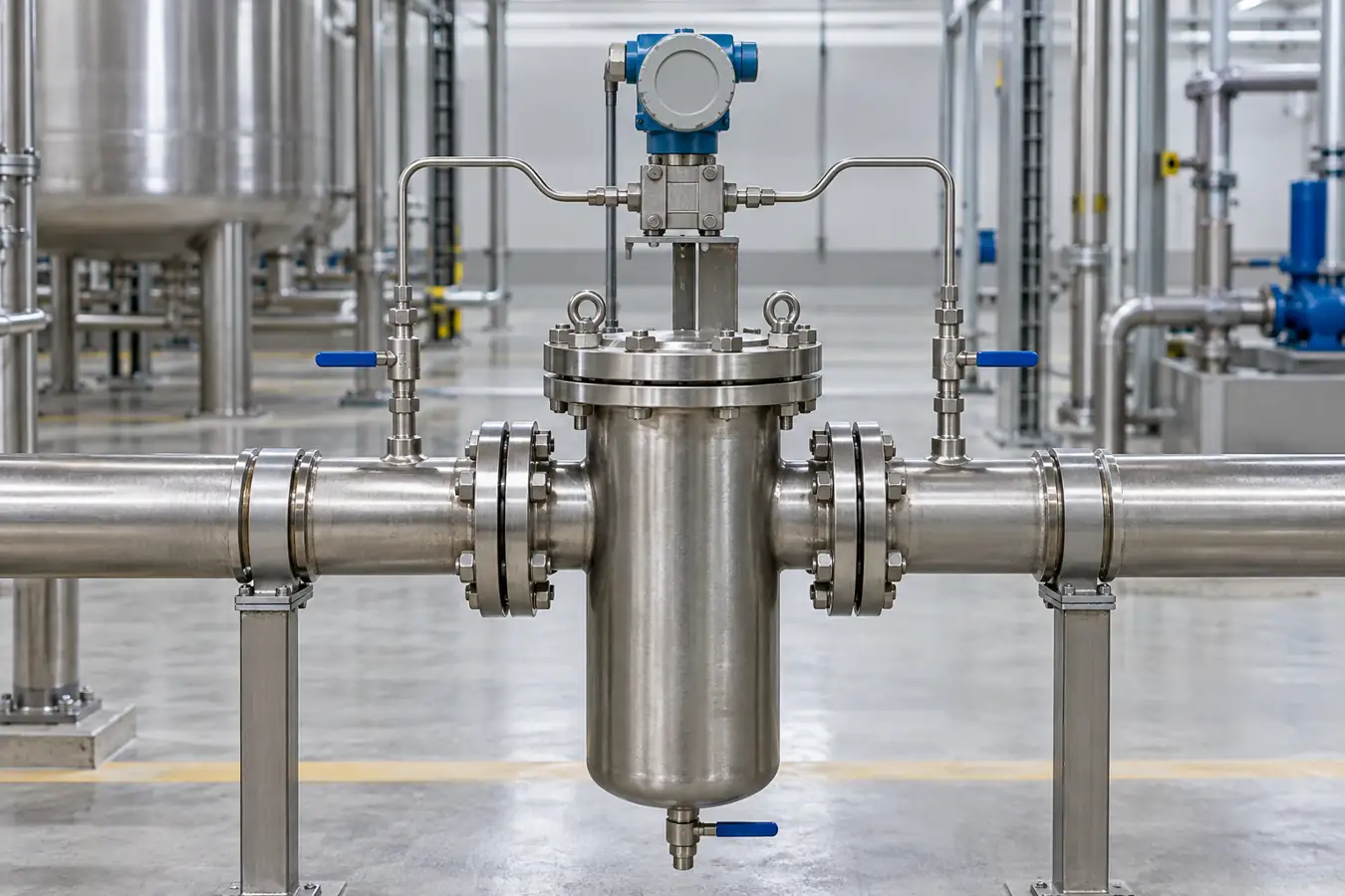
Definieren Sie die beiden Druckpunkte und die Entscheidung
Bei einem Differentialsender mit High- und Low-Ports beträgt die gemeldete Differenz konventionell ΔP = P(H) − P(L). A positive result means pressure at the H port is higher than at the L port; a negative result means the reverse. The sign depends on the connections and the instrument's convention, so label both taps and the controller input.
A differential pressure across a filter may increase as resistance to flow increases. However, the reading also depends on flow rate, fluid properties and operating conditions. A higher value is not automatically proof that the filter alone has become blocked. Compare at similar operating conditions and use the equipment manufacturer's maintenance criteria.
| Messauftrag | Druckstellen | Was die Nummer unterstützen kann | Zusätzliche Informationen erforderlich |
|---|---|---|---|
| Filterüberwachung | Vor und nach dem Filter. | Trend des Druckverlusts unter vergleichbaren Strömungsbedingungen. | Durchfluss, Medium, Filterspezifikation und Betriebszustand. |
| Raumdruckbeaufschlagung | Kontrollierter Raum und definierter Referenzraum. | Trenddruckdifferenz und -richtung. | Türzustand, Luftstrom und anwendbare Einrichtungskriterien. |
| Strömungselement | Zwei Klicks auf ein konstruiertes Primärelement. | Infer flow using the element's validated relationship. | Fluideigenschaften, Elementgeometrie, Installation und Berechnung. |
| Tankfüllstand | Geeignete Flüssigkeits- und Referenzseitendrücke. | Hydrostatischen Druck unter einer definierten Anordnung ableiten. | Flüssigkeitsdichte, Hahngeometrie, Gasdruck und Zustand der Referenzlinie. |
Bei vielen Differenzdruck-Durchflusselementen ist der Durchfluss unter den Bedingungen der anwendbaren Berechnung ungefähr proportional zur Quadratwurzel des Differenzdrucks. Es handelt sich nicht um eine universelle direkte Eins-zu-eins-Konvertierung. Differenzen nahe Null, Offsets und Unsicherheiten können einen großen Einfluss auf den abgeleiteten geringen Durchfluss haben. Neben dem Messumformer müssen auch das Primärelement, die Flüssigkeitseigenschaften und die Installation berücksichtigt werden.
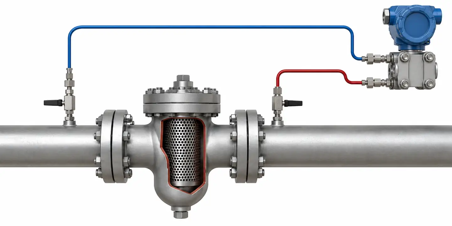
Getrennter Messbereich vom Druckwiderstand
Die Differenzmessspanne beschreibt die Differenz, die der Sensor messen soll. Statischer oder Gleichtaktdruck beschreibt den Druck, der an beiden Anschlüssen zusammen anliegt. Ein Prozess kann eine kleine Differenz aufweisen, während auf beiden Seiten ein hoher Druck herrscht. Beispielsweise erzeugen ein Vordruck von 10 bar und ein Hinterdruck von 9,9 bar einen Unterschied von 0,1 bar, während an beiden Anschlüssen immer noch Drücke in der Nähe von 10 bar herrschen. Diese Werte dienen der Veranschaulichung; Es handelt sich hierbei nicht um Bewertungen für ein bestimmtes Gerät.
Diese Unterscheidung ist wichtig, da ein Sensor möglicherweise eine ausreichende Differenzspanne, aber einen unzureichenden maximalen Arbeitsdruck oder eine einseitige Überlastgrenze aufweist. Während des Startens, Herunterfahrens, der Wartung oder einer Blockade kann an einem Anschluss ein ganz anderer Druck herrschen als am anderen. Notieren Sie den Normal- und Maximaldruck bei jede Verbindung, erwartete Übergangsbedingungen, maximale Differenz und vom Hersteller definierte Grenzwerte. Gehen Sie niemals davon aus, dass der Berstdruck eine normale Betriebsgrenze darstellt.
Der Yokogawa EJA130E Produktinformationen listet Differenzmessungen, statische Druck- und Druckgrenzinformationen separat auf. Die veröffentlichten Zahlen gelten für das angegebene Modell und die angegebene Konfiguration. Konsultieren Sie die genauen Spezifikationen für die ausgewählte Kapsel und Option. Ein Niederdruckluftgerät wie das Johnson Controls DP150 ist für eine andere Gebäudesteuerungsanwendung konzipiert. Ähnliche Kennzeichnungen machen die Geräte nicht austauschbar.
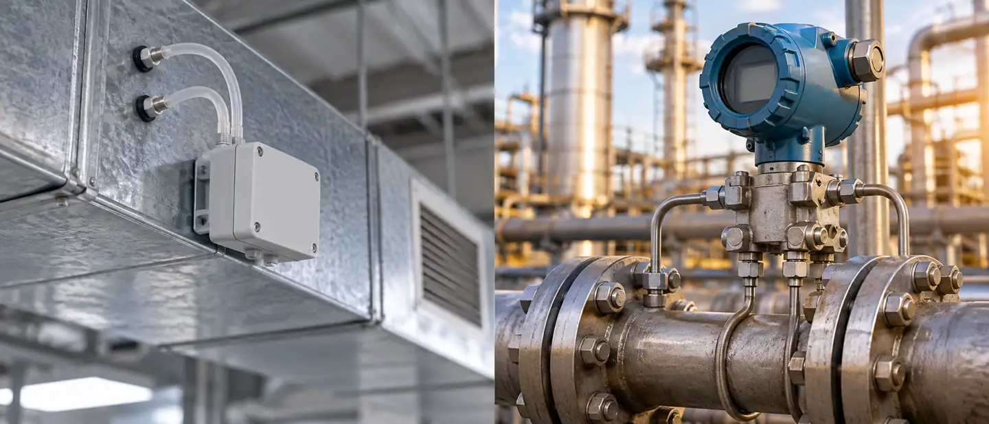
Was Sie in einer Spezifikation verlangen sollten
- Differenzmessbereich, einschließlich der Frage, ob negative Werte benötigt werden.
- Maximaler Arbeitsdruck und ob er für beide Anschlüsse zusammen gilt.
- Maximale einseitige Differential- oder Überlastbewertung in jede Richtung.
- Temperatur- und Medienbedingungen liegen hinter den angegebenen Nennwerten.
- Druckanschluss, benetzte Materialien, Dichtungs- und Montageanforderungen.
- Referenzgenauigkeitsbasis, Temperatureffekt, statischer Druckeffekt und Langzeitstabilität.
- Ausgangstyp, Spannungsversorgung, Reaktionszeit, galvanische Trennung und Fehleranzeige.
Manufacturers may use different definitions for “overpressure,” “proof pressure” and “burst pressure.” Use the definitions in the actual datasheet and do not substitute one for another. A sensor's ability to survive an exceptional event does not necessarily mean it remains accurate immediately afterward.
Wählen Sie einen sinnvollen Differenzbereich
Choose the narrowest range that covers the expected measurement and credible transients while meeting the device's pressure limits. An unnecessarily wide span can make a small working signal difficult to distinguish from offset, noise or a percentage-of-span error. A span that is too narrow can saturate during startup or process upsets and leave no useful indication of the event.
Beginnen Sie mit einem normalen Betriebsband und dem Entscheidungspunkt. Ein Filtersystem kann eine saubere Betriebsbasislinie, ein Wartungsentscheidungsniveau und eine höhere vorhersehbare Störung aufweisen. Ein Raumdrucksystem muss möglicherweise kleine positive und negative Unterschiede um Null herum erkennen. Fragen Sie, ob das Instrument einen bidirektionalen Bereich unterstützt und wie es Messwerte außerhalb des ausgewählten Maßstabs meldet.
Einige Mehrbereichssender ermöglichen eine vor Ort wählbare Spanne. Bestätigen Sie, ob sich der Genauigkeitsanspruch mit dem ausgewählten Bereich ändert, ob die Ausgabe automatisch neu skaliert wird und ob der Controller aktualisiert werden muss. Notieren Sie die Einstellung am Sender und im Steuersystem. Ein korrekter Sensor, der an einen falsch skalierten Analogeingang angeschlossen ist, kann einen plausiblen, aber falschen technischen Wert erzeugen.
Lesegenauigkeit im Kontext des tatsächlichen Signals
Eine Genauigkeit, die als Prozentsatz des Skalenendwerts oder der kalibrierten Spanne ausgedrückt wird, ist nicht dasselbe wie ein Prozentsatz des Messwerts. Als einfache Berechnung nehmen wir an, ein Gerät verfügt über eine ±1 % der 100-Pa-Spanne reference accuracy under stated conditions. That component is ±1 Pa. At a 10 Pa reading, ±1 Pa represents 10% of that reading. This is arithmetic for an illustrative specification, not an estimate of a particular sensor's installed performance.
Die Referenzgenauigkeit kann Nichtlinearität, Hysterese und Wiederholbarkeit unter definierten Laborbedingungen kombinieren. Dabei können Temperatureffekte, statische Druckeffekte, Montageeffekte, Drift, Stromversorgung und die Unsicherheit der Testreferenz ausgeschlossen werden. Der Johnson Controls DP150-Spezifikationen Identifizieren Sie die Grundlage der angegebenen Genauigkeit für diese Serie. Der WIKA CPT8900-Spezifikationen show that high-accuracy instruments can state separate static and differential characteristics. Compare like with like and check the actual model's conditions.
Addieren Sie nicht automatisch jede Datenblattnummer, als ob alle Fehler immer in die gleiche Richtung auftreten würden, und gehen Sie nicht davon aus, dass unabhängige Fehler immer durch die Wurzelsummenquadratkombination kombiniert werden können. Ein aussagekräftiges Unsicherheitsbudget hängt von den Spezifikationsdefinitionen und der Anwendung ab. Identifizieren Sie für eine kritische Entscheidung die wichtigsten Mitwirkenden und verwenden Sie eine dokumentierte, für das Projekt geeignete Methode.
Statischer Druck und Nullpunktverschiebung
Wenn beide Anschlüsse einem großen gemeinsamen Druck ausgesetzt sind, kann der Messumformer einen statischen Druckeffekt aufweisen, selbst wenn die Differenz klein ist. Eine Nullprüfung bei atmosphärischem Druck beschreibt das Verhalten beim Arbeitsleitungsdruck möglicherweise nicht vollständig. Der Rosemount 3155 Referenzhandbuch Enthält eine modellspezifische Diskussion der Nullpunktkorrektur bei hohem statischem Druck. Das zulässige Verfahren hängt vom Sender und der Prozessanordnung ab; Verwenden Sie das aktuelle Handbuch und die Vorgehensweise vor Ort.
Das wiederholte Justieren des Nullpunkts ist kein Ersatz für die Suche nach einem Leck, einer Verstopfung, einer ungleichen Flüssigkeitssäule oder einer geänderten Installation. Bevor Sie eine Einstellung vornehmen, notieren Sie die Ist-Anzeige und vergewissern Sie sich, dass an beiden Anschlüssen tatsächlich der beabsichtigte gleiche Druck unter den angegebenen Bedingungen herrscht. Bewahren Sie das Ergebnis und die Bedingungen im Originalzustand für einen späteren Vergleich auf.
Ein Differenzsensor oder zwei unabhängige Drucksensoren?
Das Subtrahieren zweier separater Druckmessungen ist möglich, aber jeder Sensor trägt zur Unsicherheit des Ergebnisses bei. Betrachten Sie zwei Sender, die jeweils etwa 10 bar anzeigen, während die interessierende Differenz 0,1 bar beträgt. Ein kleiner Versatz an beiden Eingängen kann einen erheblichen Bruchteil der berechneten Differenz ausmachen, auch wenn jeder einzelne Druck angemessen erscheint. Die beiden Kanäle können auch unterschiedliche Temperaturreaktionen, Drift- oder Abtastverzögerungen aufweisen.
A dedicated differential transmitter measures the pressure difference as its primary variable. It still has offset, temperature and common-pressure effects, and it must be rated for the pressure applied at each port. It is not automatically superior for every job: two sensors can be useful where individual pressures are needed or where their uncertainty is demonstrably acceptable. Compare the actual error budgets, installation and safety requirements for the intended decision.
Verwenden Sie für eine Subtraktion in einem Controller kompatible Druckreferenzen und synchronisieren Sie die Messwerte. Das Subtrahieren eines absoluten Drucks von einem Manometerdruck ohne Berücksichtigung der unterschiedlichen Referenzen ist keine gültige Differenzmessung. Dokumentieren Sie außerdem, was passiert, wenn ein Signal fehlt oder außerhalb der Reichweite liegt. Ein Controller sollte einen ausgefallenen Kanal nicht stillschweigend als echte Null behandeln.
Die Impulsleitungen sind Teil des Instruments
Druckanschlüsse, Schläuche, Ventile und Armaturen leiten die beiden Prozessdrücke zum Messelement. Ein Messumformer kann einen Druck nicht korrigieren, der seinen Anschluss nie erreicht, weil eine Leitung verstopft, undicht oder isoliert ist. Die Lage und der Zustand beider Wasserhähne haben daher Einfluss auf die Bedeutung der Ablesung.
For a gas service, accumulated liquid can create unwanted hydrostatic head or a blocked path. For a liquid service, trapped gas can affect response and stability. Steam and high-temperature services often require arrangements determined by the equipment manufacturer and site engineering practice. Unequal liquid columns, temperature differences and long tubing runs can contribute offsets or delays. The precise design depends on the fluid, pressure, temperature and process safety requirements.
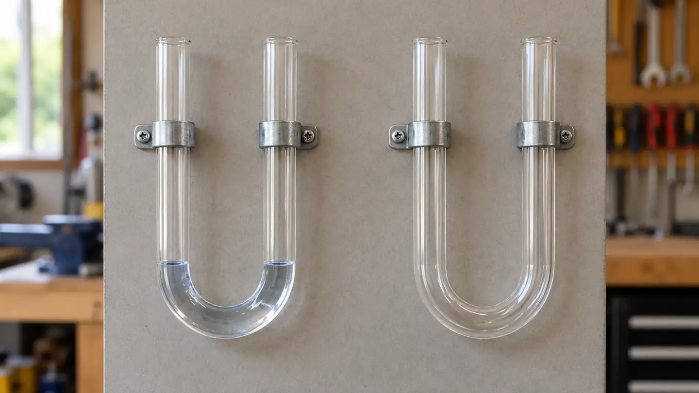
Place taps where they represent the intended pressure difference and can be inspected. A tap in a stagnant pocket may see accumulated solids; one near strong turbulence or a bend may not represent the pressure assumed by a flow-element calculation. Protect lines from mechanical damage and route them so that inspection and maintenance are practical. Follow the applicable primary-element and transmitter manuals for tap orientation, manifold design and commissioning.
Do not open or equalize process connections based on a generic online checklist. Pressurized, hot, toxic or flammable systems require site-specific isolation and operating procedures. A visual review of a trend does not establish that an impulse line is safe to service.
Choose materials, mounting and electrical output together
For liquid or gas process service, confirm compatibility of diaphragms, seals, fittings and any fill fluid with the actual medium, cleaning chemicals and temperature. If a diaphragm seal is required, its capillary and fill-fluid temperature behavior become part of the measurement chain. An installation with aggressive cleaning cycles can differ from a nominal room-temperature datasheet condition.
Mount the instrument according to its manual. A change in orientation or a mechanically stressed connection may affect zero for some low-range devices. An enclosure rating does not automatically establish chemical compatibility or suitability for every washdown method. Consider vibration, condensation, sunlight, accessibility and the environment around electrical connectors.
Analog outputs such as 4–20 mA or voltage signals and digital outputs each require a matching controller input. Verify the supply, wiring, load limits, signal range, units and fault state. With a 4–20 mA output, determine whether the controller interprets the lower and upper values as the intended engineering range and whether an out-of-range current indicates a measurement or fault condition. The specific behavior belongs to the transmitter and controller manuals.
Compare a filter application with a room-pressure application
In a filter application, the required pressure points lie on opposite sides of an element. The useful signal is the loss across that element at an identified operating flow. Before choosing a range, collect expected clean and maintenance-condition values from the filter or system documentation, then consider startup and abnormal-flow conditions. A sensor mounted on a bypass with both lines routed to the same side of the filter can show a credible number that answers the wrong question. A process sketch with clearly identified taps is therefore part of the specification.
In a room-pressure application, a small change around zero can reverse the inferred pressure direction. Doors, reference-space pressure and ventilation operating modes may affect the reading. Bidirectional range, low-end offset and stability may matter more than a large maximum span. Determine whether the decision is based on a brief indication, a sustained trend or an alarm; then evaluate the sensor and control system at the relevant timescale. Do not infer a particular room's compliance from a generic differential-pressure threshold.
These examples also show why a signal's physical meaning should be recorded with its units. “Pressure 20 Pa” is incomplete without two locations and a sign convention. Across a filter it describes a loss; between rooms it describes their relative pressure. If either tap is moved, label the resulting series so that the apparent step is not mistaken for a process change.
Scaling and sign: an illustrative calculation
Suppose a transmitter is configured for −100 to +100 Pa and produces 4–20 mA linearly across that range. Under that stated configuration, 4 mA corresponds to −100 Pa, 12 mA to 0 Pa and 20 mA to +100 Pa. If a controller mistakenly assumes a 0 to 200 Pa scale, the same 12 mA signal will display 100 Pa rather than zero. The instrument and control system may each be functioning correctly, yet the combined indication is wrong.
This example does not prescribe an output configuration for every model. Some devices offer other scales or fault-current behavior. During commissioning, record the configured lower and upper range values, units and output convention at both ends of the signal path. Confirm at several suitable test points, including zero and the region where a decision is made. A wiring or scaling check is separate from a pressure-path check: either can pass while the other remains wrong.
Commissioning and verification

Commissioning should establish the instrument configuration and the installed measurement path. Record the model, serial number, port assignments, selected range, output scaling, mounting position, medium and relevant pressure and temperature conditions. Confirm that both pressure paths are connected to their intended taps and that the controller's engineering units match the transmitter configuration.
Verification uses a suitable reference to compare the output at specified points, including the working region and zero when appropriate. Check the reference instrument's range and uncertainty; it should be suitable for the tolerance being evaluated. A laboratory comparison at atmospheric pressure is useful but may not capture field effects from common pressure, impulse lines and process temperature. Record the conditions so the result is not mistaken for a complete installed-system validation.
Check the reference and document the result
Choose a reference that covers the test range and has uncertainty appropriate to the acceptance tolerance. A reference instrument with a wide range may be insufficiently precise at a very small differential even if it can display the value. Calibration records should identify the reference, its status, the applied points and the environment. For an analog output, record both the actual electrical signal and the controller's displayed engineering value when the purpose is to validate the entire chain.
Where safe and technically appropriate, compare increasing and decreasing test points to reveal hysteresis or a stuck mechanism. Allow the instrument and reference to stabilize as their procedures require. A rapid check may show whether the system responds but cannot by itself establish long-term stability or its complete uncertainty over temperature and static pressure. Report what was actually checked and avoid extending the conclusion beyond the test conditions.
An as-found result is valuable even if the instrument later passes after adjustment. It shows whether earlier data might have been affected and whether the verification interval is appropriate. Preserve the original configuration, the reason for adjustment and the as-left check. If a pressure line was cleaned or replaced at the same time, record that intervention separately: a better reading may be due to the restored pressure path rather than an electronic calibration change.
| Symptom | Possible causes to investigate | Evidence that helps |
|---|---|---|
| Negative value where positive was expected | Reversed ports, actual flow reversal or sign/scaling configuration. | Tap labels, process direction and transmitter configuration. |
| Flat value despite process change | Blocked line, closed isolation, saturation, frozen output or real process stability. | Status flags, signal checks and qualified inspection of the pressure paths. |
| Slow response | Long or partially blocked line, damping, trapped gas or process behavior. | Response comparison and line condition under approved procedures. |
| Shift after maintenance | Mounting change, line fill, temperature, zero or configuration change. | As-found/as-left records and documented installation conditions. |
| Noisy signal | Pulsation, vibration, electrical interference or unsuitable damping. | Raw signal, process operating state and wiring inspection. |
Troubleshoot the complete chain before replacing or recalibrating the transmitter. The ICS Schneider discussion illustrates why incorrect pressure paths and zero conditions can resemble a defective sensor. Its examples are diagnostic prompts, not a substitute for the procedures and limits of your installation.
A procurement worksheet
Before requesting a quotation, state the medium and purpose; mark the H and L taps on a process sketch; specify the minimum, normal and maximum differential; list normal and maximum static pressure at each port; and describe credible one-sided pressure events. Include the working temperature, cleaning chemicals, materials, electrical output and required response time.
Next, define the required uncertainty at the decision point rather than asking only for a high accuracy percentage. Include expected ambient and process conditions, calibration interval and reference availability. Ask the supplier to identify which specifications apply to the exact part number and which conditions are excluded. Finally, record who will install, inspect and verify the pressure paths over the sensor's working life.
Preserve context in the long-term record
Store the two tap locations, sensor orientation, range and units with the signal tag. Include the active configuration and a dated note when the instrument, primary element, pressure lines or controller scaling changes. A trend that shifts after a maintenance event is easier to interpret when the record shows whether a line was cleaned, a transmitter was re-ranged or a filter was replaced.
For filter monitoring, record the flow or operating mode alongside differential pressure. Comparing a reading at low flow with one at high flow can exaggerate or conceal the effect of filter loading. For a room, record ventilation mode and relevant door events where practical. For a flow element, retain the calculation configuration and the fluid-property basis. These supporting variables let an operator distinguish a change in the process from a change in the conditions under which the pressure was measured.
For a broader HVAC context, the guide to interpreting HVAC pressure readings discusses how air, refrigerant and hydronic pressure readings answer different questions.
Häufig gestellte Fragen
Is differential pressure the same as gauge pressure?
No. Differential pressure compares two defined pressure points. Gauge pressure compares a pressure with local atmospheric pressure. A device may measure a difference relative to atmosphere, but its configuration and reference must be stated.
Can I subtract two independent pressure sensors?
Sometimes, if their ranges, references, timing and combined uncertainty suit the task. When the desired difference is small relative to each sensor's range, offsets and drift can dominate the subtraction. Evaluate the entire measurement uncertainty before assuming two general pressure sensors are adequate.
Why can a small differential require a high-pressure-rated transmitter?
Beide Anschlüsse können unter einem hohen gemeinsamen Druck stehen, während ihr Unterschied gering ist. Die Differenzspanne beschreibt die gemessene Differenz; Die Arbeits- und Überlastwerte beschreiben die Druckfestigkeit unter definierten Bedingungen.
Bedeutet eine höhere Filterdifferenz immer, dass der Filter verstopft ist?
No. A filter's pressure drop also depends on flow and other operating conditions. Compare similar states and follow the filter manufacturer's criteria.
Behebt die Nullpunkteinstellung eine blockierte Impulsleitung?
Nein. Durch die Nullpunkteinstellung kann ein repräsentativer Prozessdruck in einem verstopften oder undichten Pfad nicht wiederhergestellt werden. Überprüfen und verifizieren Sie die Messkette anhand des geltenden Verfahrens vor Ort, bevor Sie die Kalibrierung ändern.
Wie oft sollte ein Differenzdrucktransmitter überprüft werden?
Use the manufacturer's instructions, site requirements, process risk and observed stability to establish an interval. Maintain verification records and revise the schedule when evidence supports it.










Hinterlasse eine Antwort