
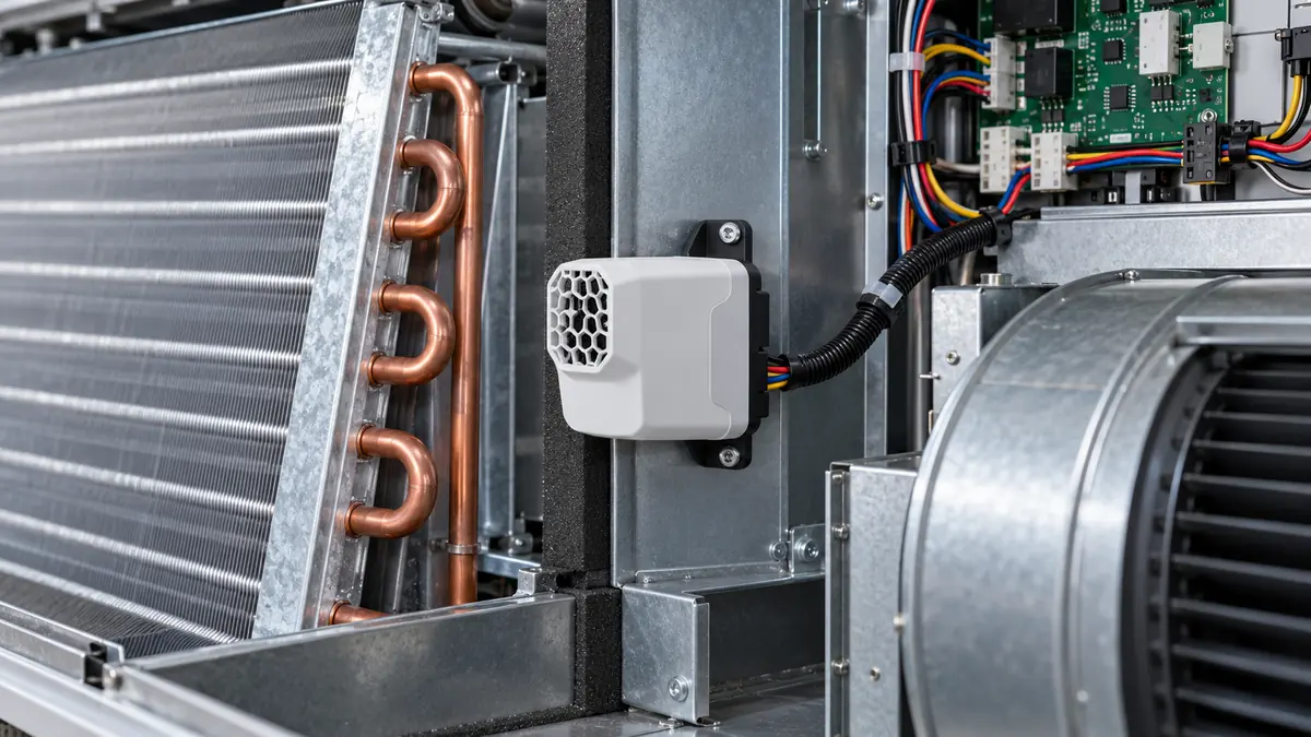
Integrating a refrigerant detection module means much more than connecting power and reading a gas value. The equipment designer must define the refrigerant and safety function, place the inlet where an applicable release can reach it, maintain the module's environmental and electrical conditions, interpret alarm and fault states separately, and verify that the host equipment performs the intended response. A sensor module is one part of that chain. Its data sheet alone does not establish that the completed air conditioner, heat pump or refrigeration unit meets a particular equipment requirement.
This article is for OEM engineers and technically responsible integrators planning an embedded detector. It offers a design-review framework rather than a universal wiring diagram or field gas-test method. The exact product variant, equipment listing, adopted standard, installation instructions and qualified test procedure determine final choices. If you are choosing the sensing principle or target gas first, our refrigerant sensor selection guide provides the earlier measurement-task questions.
Define the complete function before choosing a module
Start with the equipment and refrigerant, not a generic catalog category. Is the proposed sensor intended to support an integral safety-related refrigerant detection system, an area monitor for maintenance awareness, or a service diagnostic function? Does the host need a quantitative concentration, a binary alarm, a fault state, or more than one of these? Which controller decides to start a fan, open a damper, disable an ignition source or stop a compressor? These are system questions. A sensor that can detect the target gas is not automatically a suitable system input for every action.
UL Solutions' discussion of integral refrigerant detection systems explains that, where an integral RDS is required for certified HVAC equipment, sensors and mitigating actions are evaluated as part of the equipment and installed according to that equipment's instructions. Its examples of placement and timing are tied to the applicable equipment and standard context. Do not copy one quoted threshold or location into a different product without checking the actual listing and current requirements.
The first design document should identify the complete chain:
| Layer | Question to resolve | Evidence to keep |
|---|---|---|
| Refrigerant and use case | Which gas or blend, equipment orientation and occupied-space or cabinet scenario? | Refrigerant designation, equipment risk analysis and configuration revision |
| Sensing module | What concentration/profile, environmental range and health states are supported? | Exact data sheet, model suffix, firmware and test report scope |
| Gas path | Can a credible release reach the inlet in each installation orientation? | Location rationale, airflow/obstruction review and installation drawing |
| Electrical link | Does supply and communication remain valid across operating states? | Interface specification, wiring diagram, power and fault tests |
| Host logic | What does the controller do for gas alarm, sensor fault and lost communication? | State table, software revision and acceptance test |
| Actuator and feedback | Did commanded mitigation actually occur? | Fan/damper output and available feedback record |
| Service life | How is a failed, contaminated or replaced module recognized? | Maintenance, replacement and requalification procedure |
This table is not a compliance checklist copied from a standard. It is a way to make the system boundary visible. A product brochure may address the sensing-module row well but say nothing about the host logic or actual airflow after an alarm.
Match the exact refrigerant profile to the intended measurement
“Refrigerant detector” is not one gas specification. R-32, R-454B, R-290, R-717 ammonia and R-744 carbon dioxide differ in chemistry, safety classification and measurement objective. A module designed for one gas may respond to another, but response alone is not proof of calibrated, safety-related performance. For a blend, the configured profile and alarm basis must match the approved equipment design. If the system reports %LFL, the percentage is relative to the defined refrigerant and its lower flammability limit; it cannot be reassigned to a different gas by changing a screen label.
El Winsen ZRT512E R-32/R-454B product information illustrates why suffixes and profiles matter. It states the target refrigerants, NDIR principle, RS485 interface, supply and environmental conditions for particular variants. It also qualifies operating humidity as noncondensing. Those statements are useful for a design review of that model. They do not establish that another NDIR module has the same power needs, response or approvals. A mixed fleet of refrigerants should be documented at equipment level before a single module family is selected.
Interference is part of the profile review. Another refrigerant, cleaning vapor, temperature transient or contamination can produce a misleading indication or alter later target response, depending on the device. Ask for the exact model's gas matrix and post-exposure test conditions. Our cross-sensitivity guide explains how to read those claims without treating a suspected interferent as proof that an alarm is false.
Preserve the gas path, not only the mechanical fit
The module has to encounter representative gas. Its inlet may use diffusion openings, a membrane, filter or a forced sample path. Mounting a compact board behind an attractive cover can slow or block gas transport even if the electrical pins remain accessible. Cabinet airflow, coil geometry, fans, condensate, foam insulation and field installation orientation can all alter what reaches the sensing element. A module's test-chamber response time does not automatically equal the complete equipment's response after installation.
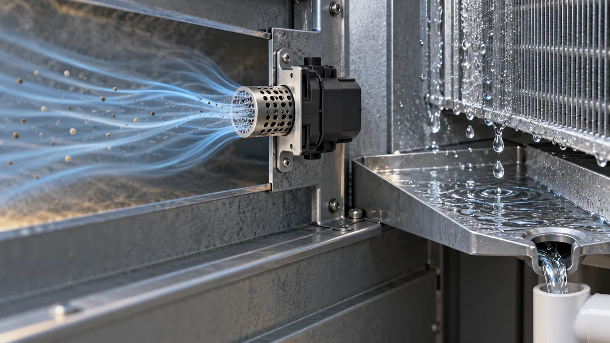
Map plausible release points and the air paths they create in each equipment orientation. Ask whether a leak could remain behind a partition while the module samples a well-ventilated section, or whether an indoor fan could carry gas toward the sensor only in certain modes. The answer is product- and scenario-specific. UL's inspector guidance highlights that field orientation of convertible equipment can change the prescribed sensor position. A cabinet that can be installed upflow or horizontally should not assume one physical location remains valid without the equipment manufacturer's instruction.
Consider the inlet's exposure to water. Cooling coils deliberately collect condensate, but a refrigerant sensor's inlet may not tolerate liquid droplets. An enclosure rating does not automatically say that its gas-diffusion path can operate submerged or wet. The Sensor1stop guide to condensation around HVAC sensors distinguishes intended coil drainage from unwanted sensor wetting. For a safety-related detector, a blocked or wetted inlet needs the prescribed fault and service response, not an assumption that no gas is present because the display is low.
Service access belongs in the layout. Can a qualified technician inspect, replace or verify the module without damaging the inlet, wiring or sealed section? Is there space for the connector and strain relief in every installation orientation? Can the module be identified by model and serial number after the equipment is installed? A design that is easy to assemble at a factory but nearly impossible to inspect in service can weaken long-term system availability.
Design the power and interface as a monitored boundary
An embedded module may expose a voltage, current, PWM, UART, RS485, relay or proprietary digital interface. Each choice carries different wiring, noise, timing and diagnostics. A serial link can carry a concentration value and explicit status flags, but the host must know which message version and gas profile it is reading. An analog output may be simple to acquire but needs documented scaling and a strategy to distinguish valid zero from open-circuit or out-of-range conditions. A relay may convey a decisive alarm but cannot by itself explain concentration history or module health unless separate contacts are provided.
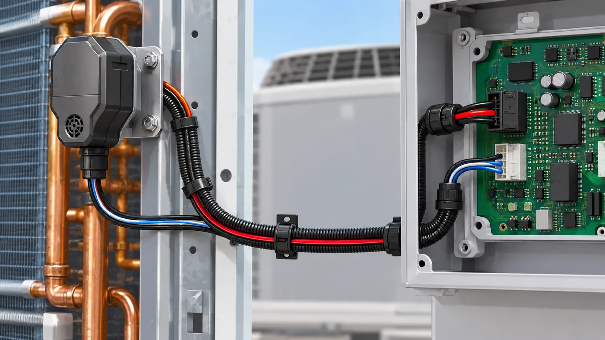
The module's supply tolerance and startup current must be checked against the actual controller board and cable length, including low-voltage conditions during fan or compressor transitions. Grounding, isolation, shielding and connector retention follow the product and equipment design. A supply that looks adequate on a bench may dip during a real startup. Likewise, a communication link that works with a short lab cable may suffer errors near variable-speed drives or long field wiring. Testing should include the electrical environment the module will experience, without assuming that a generic RS485 label guarantees interoperability.
Texas Instruments' A2L sensor-module design brief illustrates the optical sensor, signal conditioning, microcontroller and communication portions of an example design. It is an explanation of a design architecture, not certification of a finished detector. The OEM still needs to specify message framing, update interval, timeout, startup state, invalid-value encoding and firmware compatibility for its selected module.
Keep a protocol register in the design file. It should identify module address or identity where relevant, data units and scaling, signed/unsigned formats, status bits, communication timeout and what the host does when a message is stale. A value displayed as “0” after a lost link is a serious ambiguity if the controller does not also show a communication fault. The same applies to a module during warm-up: it may not yet be making a valid measurement, even though power is present. The host state machine should represent that explicitly.
Map gas alarm, fault and ordinary operation separately
The controller should not collapse every abnormal input into one general “sensor issue.” Gas above the configured criterion, module self-test failure, disconnected cable, out-of-range value, stale digital message and maintenance mode can have different meanings. The approved equipment design must state what happens in each state, what the user sees, what the controller commands and whether a reset is allowed. This can be written as a small state table before software implementation.
| Module/host state | Information needed by the controller | What the design review must confirm |
|---|---|---|
| Startup or warm-up | Measurement not yet valid, self-test progress | The controller does not treat an unready module as a verified clean atmosphere |
| Healthy measurement | Gas profile, valid value or normal state, timestamp | Unit and configuration agree with the equipment design |
| Gas alarm | Valid alarm transition, source and time | Required mitigation and notification are commanded and logged |
| Module fault | Explicit fault code or invalid status | Fault is visible and handled per the approved design |
| Lost communication/power | Timeout or supervised electrical state | A disconnected module cannot silently read as zero |
| Return to normal | Cause, status, reset/recovery condition | The system does not bypass required inspection or service |
El YORK air-handler installation instructions show a concrete example of separate normal, gas-alarm and sensor-fault LED states, plus model-specific orientation and wiring details. Those details belong to that equipment. The transferable design lesson is to preserve distinct states through the module, harness, controller and operator interface.
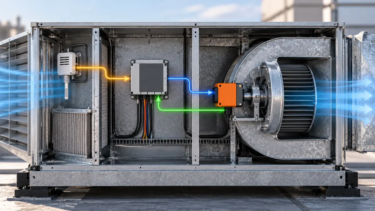
A mitigation command is not proof that the actuator worked. Where the equipment has fan, damper or relay feedback, record the commanded and observed states separately. The complete equipment test should show both the sensor input and downstream behavior. If no direct feedback is available, the design file should state that limitation rather than labeling a command as confirmed airflow.
Verify the assembled equipment, not just the board on a bench
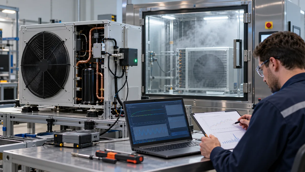
The verification plan should have levels. A component test confirms a module's stated behavior under controlled conditions. A board or harness test checks electrical supply, protocol and fault injection. An assembled-equipment test checks location, environmental exposure, controller response and mitigation outputs across operating modes. A field or production check verifies that the installed orientation and wiring match the approved configuration. Passing one level does not imply that every later level passed.
| Verification question | Example evidence to retain | Common incomplete substitute |
|---|---|---|
| Does the selected module detect the exact refrigerant/profile? | Manufacturer qualification and approved gas-response report | A broad family brochure |
| Does gas reach the installed inlet? | Equipment-specific location and airflow assessment | A bare-module response-time claim |
| Is power valid in every mode? | Minimum/maximum supply and startup test at module connector | Nominal supply measured only at controller |
| Are status and units interpreted correctly? | Protocol-version and state-transition test | One successful concentration read |
| Is communication failure recognized? | Disconnect, timeout and restoration records under approved method | Assuming a missing value is zero |
| Does equipment response occur? | Recorded command and available fan/damper feedback | Detector LED alone |
| Can the system be serviced? | Replacement and return-to-service procedure | A promised module lifetime |
For gas exposure, use the manufacturer's approved and applicable laboratory or field verification method with qualified personnel. This article does not prescribe a concentration, cylinder or release procedure. Intertek's RDS testing overview illustrates why intended response, false output and susceptibility to damage can all be within product evaluation. Confirm the tested standard edition and complete product scope before claiming that a result covers the equipment being built.
Document test conditions and revisions. A successful test on one firmware version, gas profile or cabinet arrangement may need review after an update. In production, a module installed backward, blocked by foam or connected to the wrong harness can defeat an otherwise correct design. Keep assembly instructions and checks specific enough to prevent those errors without forcing technicians to infer intent from a prototype photo.
Treat maintenance and replacement as design inputs
Module lifetime, drift, service interval and field replacement are not afterthoughts. A long advertised service life does not remove the need to detect faults or decide how the installed unit will be verified. Determine whether calibration is factory-only, field-adjustable or replaced as a complete module; identify what records and tools the operator will need. If a replacement part has a new suffix or firmware, the controller should not quietly assume identical scaling or messages.
The operator should be able to retrieve the refrigerant profile, module identifier, controller software and date of last service without opening a hazardous or inaccessible section. The product documentation should explain what a fault, out-of-range value, contamination exposure and end-of-life indication mean. If a module is disconnected for service, the host should preserve that state in its log. A gap in measurement is not a series of clean-air readings.
Preguntas frecuentes
Is an RS485 output enough to integrate a module?
No. The host needs the exact protocol, supply, wiring, units, gas profile, status values, update rate and timeout behavior. It also needs a defined response when the link is lost or the module is not ready.
Can a module's certification be used as the completed equipment's certification?
No. A component's documented testing is one input. The complete equipment's required evaluation and installation follow the applicable product standard, listing and manufacturer's instructions. Sensor location, controller logic and mitigation outputs remain system-level matters.
Can the module be hidden behind a protective cover?
Only if the completed design preserves the tested gas path and the relevant environmental protection. A cover can obstruct diffusion or trap condensate. Review the inlet and equipment orientation, not just the mechanical fit.
What if the sensor says “fault” while gas status is normal?
A fault means the channel may not be trustworthy. Do not reinterpret the last gas number as proof of a clear atmosphere. Follow the equipment's approved fault response and service procedure.
Should every HVAC product use the same refrigerant detector location?
No. Refrigerant, enclosure, coil position, installation orientation and airflow change the location question. Use the equipment's approved installation instructions and validation evidence for each configuration.
Good integration is a verified path from refrigerant exposure to equipment action, with an equally clear path for faults and maintenance. Choosing a promising module starts the work; preserving its sensing conditions and proving the complete response finishes it.
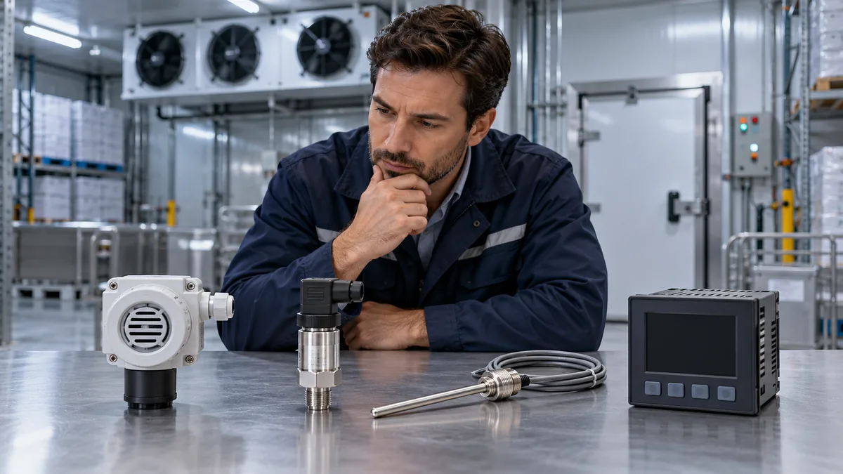
What Should a Refrigeration Monitoring Procurement Worksheet Include?
Use a decision-led procurement worksheet to compare refrigeration process, cold-room and ambient gas monitoring with verifiable evidence.
Leer más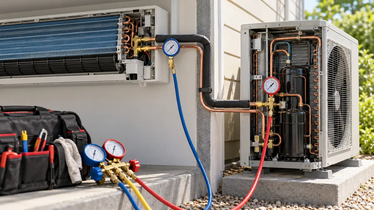
Which Pressure Readings Actually Help Diagnose an HVAC System?
Interpret HVAC pressure readings by medium, measurement point, operating mode and paired temperature before forming a diagnosis.
Leer más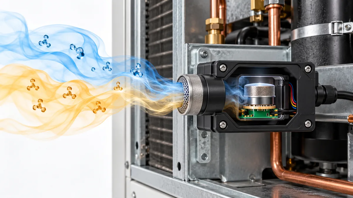
¿Puede otro gas activar un detector de refrigerante? Lectura de afirmaciones de sensibilidad cruzada
Comprenda la sensibilidad cruzada del detector de refrigerante, compare la evidencia NDIR y MOS y lea las afirmaciones sobre interferencias de gas sin descartar una alarma real.
Leer más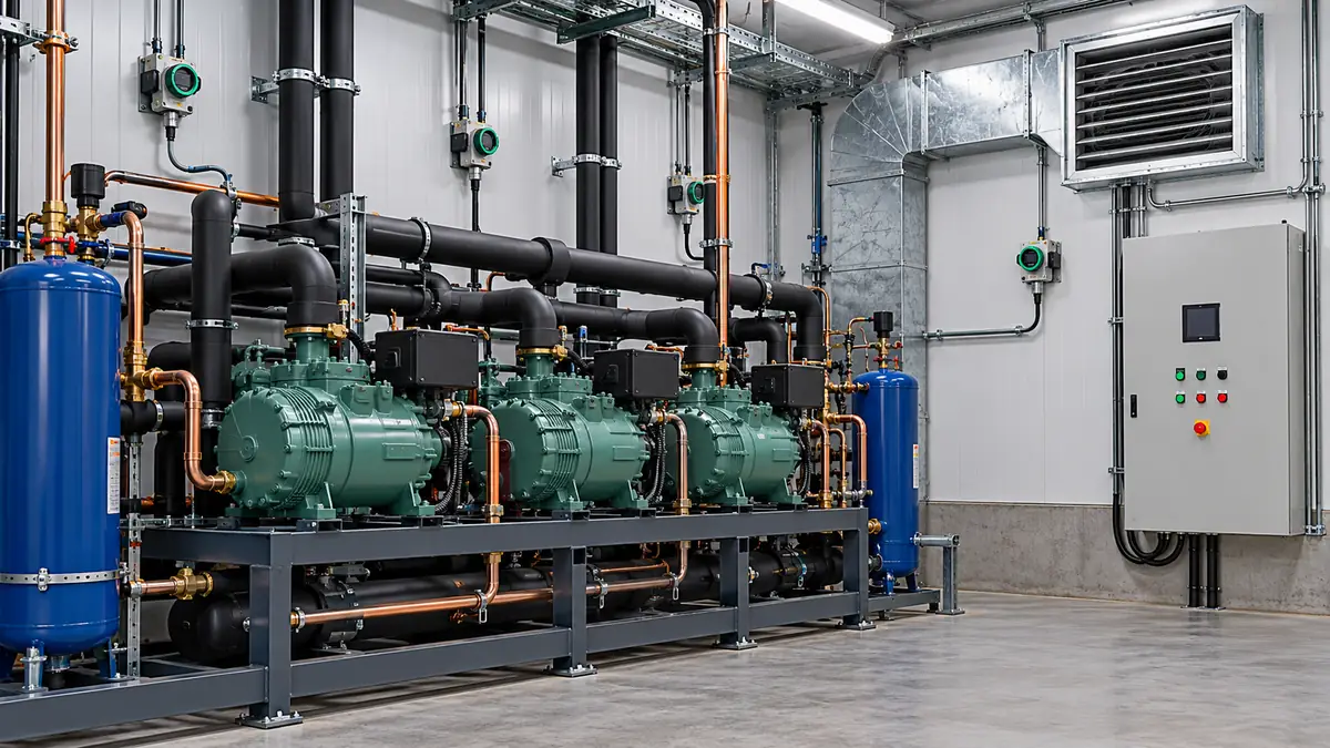
¿Qué debe registrar un registro de monitoreo de gas en la sala de una planta de refrigeración?
Cree un útil registro de gas en la sala de máquinas registrando la identidad, la configuración, las alarmas, las fallas, la respuesta de la ventilación y la evidencia de mantenimiento del detector.
Leer más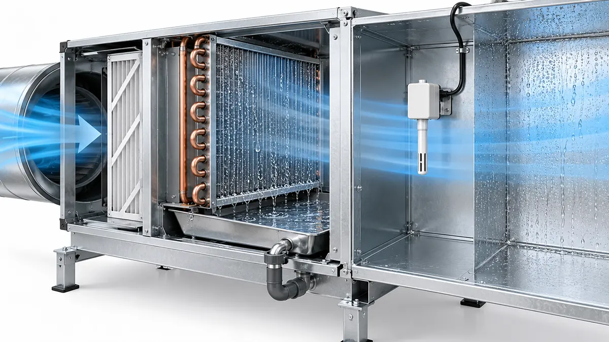
¿Cuándo la condensación engaña a un sensor HVAC?
Descubra cuándo la condensación en los serpentines, sondas y gabinetes de HVAC cambia la lectura de un sensor y cómo distinguir el drenaje esperado de la humedad no deseada.
Leer más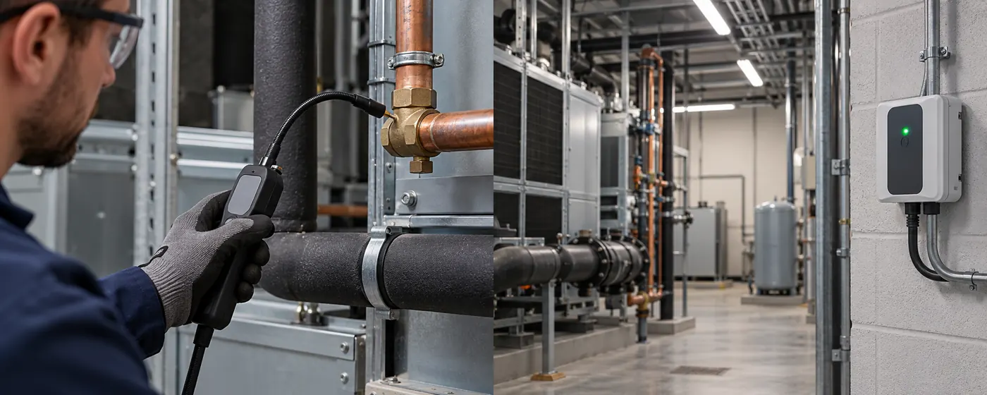
Detección de refrigerante portátil versus fija: en qué se diferencian sus trabajos
Compare localizadores de fugas portátiles, monitores de punto fijo y sistemas de aspiración por ubicación de muestra, cadena de respuesta y necesidades de puesta en servicio.
Leer más