
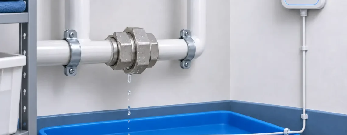
Choisissez un capteur de fuite d'eau en faisant correspondre le liquide, l'itinéraire que suivra une fuite et la réponse d'alarme dont vous avez besoin. Utilisez une sonde ponctuelle conductrice où l’eau s’accumule de manière fiable en un point accessible. Utilisez un câble de détection compatible là où une fuite peut apparaître le long d'un tuyau, d'un plateau, d'une limite d'équipement ou d'un chemin au sol. Prouvez ensuite que le contact réel avec l’eau produit la notification et la réponse souhaitées. Un appareil alimenté ou une application téléphonique connectée n’établit pas à lui seul cette protection.
La question de sélection la plus utile est : Le premier rejet d’eau significatif atteindra-t-il une surface de détection fonctionnelle avant d’atteindre l’actif à protéger ? That question joins sensor technology, physical installation and alarm management. It also explains why two installations using the same detector can behave very differently.
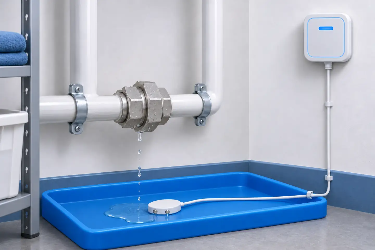
Conceptual arrangement: place the wet sensing element where water collects and keep electronics within their own environmental rating. Actual mounting details depend on the selected model.
What a contact water detector actually detects
A conductive water detector evaluates an electrical path between sensing contacts. Liquid must reach the relevant contacts and provide sufficient conduction for that particular controller to recognize a wet condition. The output usually represents water presence, rather than a measured leak rate, puddle volume or precise water depth.
This creates two separate requirements. The detector must respond to the expected liquid, and the installation must bring that liquid to the detector. A probe that works perfectly in a cup can miss a thin stream running around its housing. A cable capable of detecting water along its sensing length cannot detect a puddle stranded on the other side of a raised floor joint.
Contact detection also has a different field of view from flow monitoring, pressure analysis or an acoustic pipe survey. It does not identify every leak somewhere inside a building's pipe network. It observes water at installed sensing locations. A quiet detector therefore means no recognized wet condition at those locations, subject to the system remaining operational.
Define the protected event before specifying hardware. “Detect water collecting in the secondary tray beneath this pump” is testable. “Prevent all water damage in this room” needs several additional decisions about sources, drainage, coverage and response. Good specifications describe the event and the expected action in terms that a commissioning team can demonstrate.
Spot probe or sensing cable: choose the coverage geometry
Start with the collection area rather than the room's total floor area. A contained tray with a predictable low point often suits a spot probe. Multiple joints or an uncertain release position may favor a cable route. Some installations benefit from both: a cable near likely sources and a separate point detector at a collection sump.
| Arrangement | Where it is useful | What to verify before buying |
|---|---|---|
| Single conductive spot probe | Small drip tray, appliance recess, sump or known low point | Contact height, orientation, actual liquid compatibility and whether water can bypass the probe |
| Several point probes on separate zones | Distinct appliances or trays requiring clear identification | Number of supported inputs, zone names and fault reporting for each branch |
| Cable assembly with spaced sensing contacts | Several locations distributed along a practical cable route | Contact spacing and placement; cable between contacts may provide no sensing |
| Continuous sensing cable | Long equipment boundaries, floor channels or distributed water risks | Active sensing length, compatible controller, routing and cleaning requirements |
| Locating cable system | Larger or concealed routes where finding the wet section matters | Supported location method, route map, compatible accessories and behavior with multiple wet areas |
Do not assume that every product called a water rope has the same construction. Dorlen's Water Alert cable uses embedded sensing contacts spaced along a cable. That is a different coverage geometry from a cable whose active surface senses along its length. The product name alone cannot establish the unsensed gaps.
Nor does a cable automatically provide leak location. Some systems report only that their zone is wet. Others use compatible electronics to indicate a position or segment. The TTK FG-EC product description identifies compatible control units for its locating system. Treat that capability as a property of the specified combination.
Separate sensing cable from ordinary leader cable. A leader carries signals between the controller and the active section; it may intentionally be insensitive to water. On the installation drawing, distinguish active sections, non-sensing links, connectors and termination points. Otherwise a neat cable route can create an apparent protection boundary that water crosses without touching any active element.
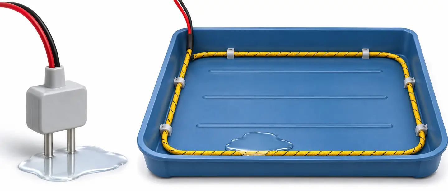
A point detector covers its contact location; a cable covers the active sensing portions specified for that product. Neither covers the empty space between the detector and the water.
Water conductivity and contact condition determine the wet signal
Water is not one fixed electrical material. Dissolved ions influence its conductivity, so potable water, condensate, treated cooling water and high-purity process water may behave differently at the same sensing element. The EPA's conductivity explanation links conductivity to dissolved inorganic constituents and identifies oil as a poor conductor. This is the physical reason a water detector should not be treated as a universal liquid detector.
Low-conductivity water needs explicit verification
Do not infer performance with distilled or deionized water from a successful tap-water demonstration. Ask for the supported liquid conductivity, the controller sensitivity conditions and the method used to establish performance. Where the manufacturer does not publish a usable limit, arrange a controlled compatibility test with a representative sample and the actual sensing/controller combination.
A useful test distinguishes two questions: can this product recognize the intended liquid, and can it do so in the installed geometry? A deep sample that completely immerses a probe does not reproduce a thin film reaching the bottom edge. Likewise, water left exposed on a dirty floor may acquire contaminants; its later behavior does not prove that the first clean release will trigger equally well.
Avoid improving the test fluid with salt or detergent simply to make the device alarm. That changes the property under evaluation and can leave residue on the sensing surface. If the available detector cannot establish reliable response to the actual liquid, consider another product or sensing principle with documented compatibility.
A conductive liquid still has to bridge the contacts
Electrode separation, wetted area and film continuity affect the electrical path. A droplet touching one contact is different from a film spanning both. Surface shape also matters: a slightly raised foot, an uneven slab or a cable held above the floor can delay contact until the puddle becomes deeper.
For this reason, minimum detectable water depth is an installed condition, not a number to borrow from another detector. Review the exact mounting orientation and any adjustable contact height. Confirm that adhesive pads, brackets or floor coverings do not lift the sensing points beyond the intended detection level.
Contamination can cause opposite failures. Conductive residue may sustain an unwanted wet indication; a water-repellent film may prevent wetting. In its Water Detector installation instructions, Primex specifically warns about foreign material such as oil or detergent on the contacts. Cleaning must restore the specified sensing surface without damaging it.
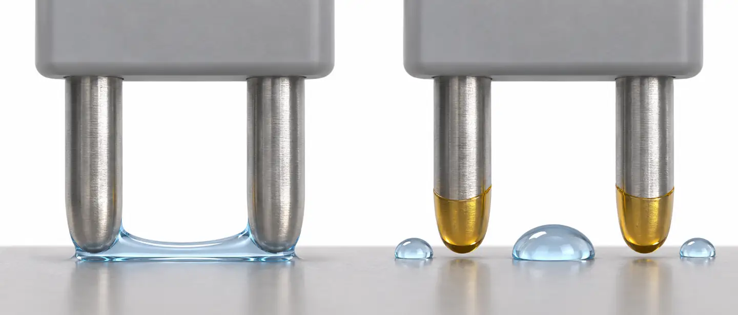
The electrical path depends on liquid contact as well as liquid conductivity. The illustration shows wetting concepts, not a threshold measurement or a particular detector design.
Place sensors along the water's likely path
Cartographiez quatre éléments ensemble : le point de rejet possible, le chemin que l'eau peut parcourir, l'endroit où elle s'accumule et l'actif qu'elle ne doit pas atteindre. Un plan d'étage qui marque uniquement les positions des tuyaux omet le chemin de transport. Un plan qui marque uniquement les coins des pièces omet de nombreux petits dégagements à proximité des équipements.
Parcourez la zone avec les personnes qui l’entretiennent. Regardez sous les panneaux amovibles là où l'accès est autorisé, inspectez les sorties des plateaux et notez les seuils, les joints de sol, les plinthes et les passages de câbles. Identifiez comment les portes, l’accès à l’équipement et le nettoyage affecteront le détecteur après l’installation. Un capteur que les techniciens écartent régulièrement ne conservera pas sa couverture d’origine.
Sous électroménager et petit matériel
For a contained appliance recess, place the sensing element where a release from the relevant hose, union or drain can actually arrive. A probe near the front may be easy to service but miss a rear leak trapped behind a raised support. Conversely, a probe directly below a normal condensate outlet may repeatedly detect expected water.
Separate ordinary operating moisture from the abnormal event. If water routinely belongs in a primary pan, a secondary containment tray may be the more meaningful detection location. Check that the secondary tray's shape directs water toward the sensor rather than around it. This is a design example, not evidence that every appliance needs the same arrangement.
Cooling units, raised floors and equipment rooms
Near cooling equipment, consider supply connections, drain blockages, condensate pumps and joints separately. A floor cable following an outer wall may detect a large spreading puddle but provide little warning for water entering a nearby floor opening first. A closer route around the relevant unit or along a channel may intercept that release sooner.
Beneath raised floors, document which panels expose the route and how technicians will inspect it. Cable location information is most useful when it translates to a recognizable panel, equipment bay or pipe section. Keep a route drawing where responders can access it during an alarm, rather than relying on someone's memory of installation day.
Overhead pipework and concealed paths
Water may track along insulation, supports or the underside of pipework before falling. Placing a detector vertically beneath one fitting does not prove it will catch every release from that fitting. Where approved, use containment or a documented sensing arrangement that accounts for the actual drip path.
Pipe-mounted cable requires a product intended for that arrangement and an installation compatible with pipe temperature, insulation and condensation. Do not copy a floor cable layout onto a pipe. Some products use capillary materials, some rely on exposed conductive surfaces, and their response and recovery conditions can differ.
Le Adeunis water leak cable datasheet, for example, describes floor, equipment and pipe applications for its specified cable. Those illustrations support that product's intended uses; they do not authorize every sensing rope to be wrapped around any pipe.
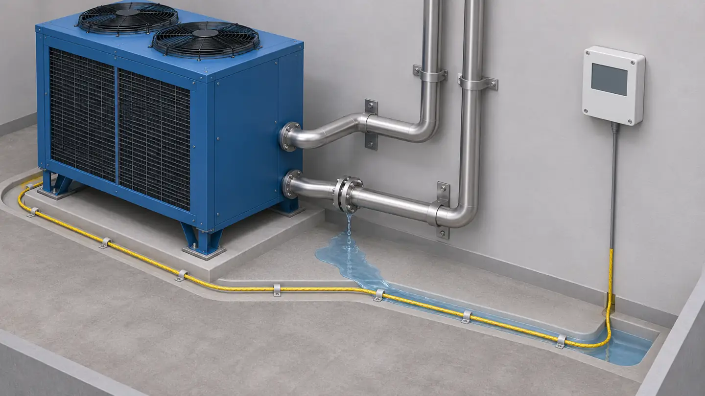
Route active sensing where a plausible release can reach it. Floor channels, barriers and openings can matter more than the distance from the nearest wall.
Specify the complete sensor-to-alarm system
A sensing cable is often one component of a larger assembly. Verify the controller, firmware requirements where applicable, cable family, maximum supported layout, connectors, branch accessories and end termination. Physical connector fit does not establish electrical compatibility.
Le Molex conductive fluid sensing cable page explicitly requires its associated water sensor rather than a direct connection to the monitoring system. This illustrates why selecting an apparently suitable cable alone leaves an incomplete specification.
Ask what each system state means. Wet, dry, disconnected, low battery and communication failure should be understood separately. A receiver displaying the last dry state is not necessarily evidence that its detector is currently reachable. Determine whether a break in the sensing run produces a fault, which parts of the circuit are supervised and how the receiving system represents that fault.
For relay integration, confirm contact ratings and the receiving input requirements. Document the intended normal and alarm contact states, including what happens when power is removed. A normally closed input can be useful in some arrangements, but its label alone does not prove supervision of every cable, sensor or power failure.
Wireless systems add another path to verify: detector to gateway, gateway to network, service to recipient. Distinguish event reporting from routine status messages. The Adeunis datasheet describes transmission when water is detected as well as periodic reporting. A heartbeat interval therefore should not be substituted for a measured alarm-delivery delay, or vice versa.
If automatic isolation is required, specify a compatible valve and a controlled response sequence separately. A water alarm output does not mean that water will stop. Confirm which supply is isolated and what equipment depends on it. The response plan should include who can inspect, reset and restore that supply after the cause has been addressed.
Install for reliable contact and practical maintenance
Begin with the surface clean and dry, and with the equipment identified on the drawing. An unexplained wet baseline should be resolved before acceptance. Inspect the sensor and cable for damaged surfaces, strained leads, crushed sections or contaminated connectors before routing them into concealed spaces.
Mount the sensing element in the orientation its manual specifies. Keep its active face exposed to the expected water. Check any restrictions on conductive floors or metal trays: unintended contact between electrodes and a conductive substrate can create an electrical path unrelated to the intended water film. Avoid covering active cable with tape, paint, sealant or a protective sleeve unless that arrangement is explicitly supported. Mechanical protection that blocks water contact defeats the sensing function.
Use the approved retainers without pinching or stretching the cable. Retention should prevent movement during ordinary cleaning and maintenance while preserving the required floor or tray contact. Account for doors, removable panels and access paths; a cable beneath a sharp panel edge can suffer damage during later work.
Place connections where they can be inspected and kept within their environmental rating. A controller may need to stay dry even when its probe is designed to get wet. Primex, for example, instructs installers to mount its Water Leak Sensor electronics above the floor because that unit is not waterproof. Use the actual product's requirement, rather than applying one vendor's mounting height universally.
Give each zone a physical name that matches the monitoring interface. “North cooling unit secondary tray” is more useful during a response than an unexplained input number. Label accessible route endpoints and save the final layout after any change. For a locating system, update the location map when sections are added, removed or rerouted.
Commission the whole alarm chain
Agree the acceptance criteria before the wet test. Define the test locations, liquid, allowed method, expected controller state, required recipients and acceptable response for the application. Manufacturer instructions take precedence over an improvised dunk test. Keep test liquid away from energized equipment and use a controlled tray or approved test aid where appropriate.
1. Establish a known dry and healthy baseline
Verify the correct detector identity, zone name and current status. Check power, battery condition where present, network connection and enabled alert rules. Confirm that the displayed information is current rather than historical. Record any inhibited outputs and the arrangement for restoring them.
2. Apply the intended wet stimulus
Use the manufacturer's method to wet the actual sensing element. A controller's test button can check downstream functions but may bypass the sensing surface and liquid contact entirely. Where compatibility with a difficult liquid matters, document the representative sample and test conditions instead of describing the liquid only as “water.”
Pour les sondes à points multiples, testez chaque emplacement requis. Pour un itinéraire distribué, sélectionnez des sections représentatives comprenant des zones éloignées ou mécaniquement difficiles, et incluez chaque zone surveillée indépendamment. Un test humide à proximité du contrôleur ne prouve pas que l'extrémité distante reste connectée ou positionnée correctement.
3. Observez chaque résultat en aval
Enregistrez le moment où l'eau entre en contact pour la première fois avec la surface active, lorsque le contrôleur indique qu'elle est mouillée et lorsque le destinataire requis reçoit la notification. Ce sont des observations différentes. Si un système de bâtiment doit afficher l'événement, vérifiez directement la zone et l'état affichés plutôt que d'accepter un clic de relais comme preuve suffisante.
Demandez au destinataire prévu d'accuser réception du message via le canal de réponse réel. Vérifiez l'acheminement en dehors des heures d'ouverture lorsqu'il fait partie des exigences. Une notification envoyée à un compte inutilisé ne fournit aucune intervention pratique, quelle que soit la précision du fonctionnement de l'élément de détection.
4. Vérifiez les défauts et l'isolation facultative séparément
Lorsque cela est pris en charge et autorisé par le plan de mise en service, simulez une déconnexion ou un défaut de communication documenté et confirmez qu'il produit l'indication de problème attendue. Ne court-circuitez pas intentionnellement des entrées non identifiées et n’interrompez pas des équipements non liés pour créer un test.
If a valve response is included, coordinate a controlled functional test with those responsible for the affected equipment. Verify the physical valve state and intended isolation, then follow the agreed restoration procedure. Alarm delivery, actuator movement and successful isolation are separate acceptance items.
5. Prove recovery
Remove the test water, clean and dry the element using the approved method, and observe the return to normal. Some systems latch alarms until acknowledgment; some sensing materials need substantial drying time. Confirm both the physical dry state and the controller's reset behavior. Restore all inhibits and verify that the next genuine event can be reported.
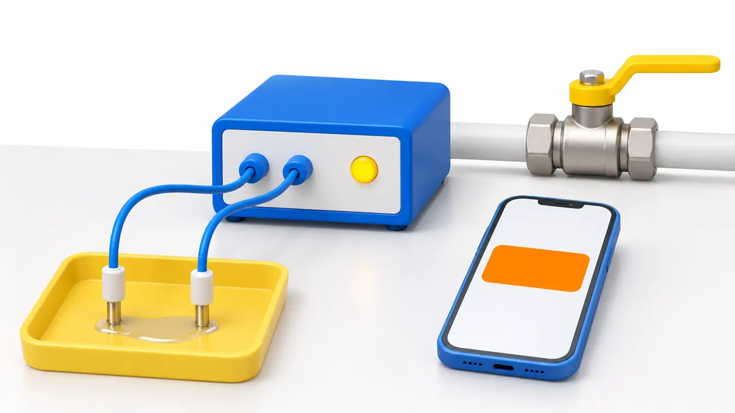
A controlled test follows the path from liquid contact through indication and notification. The valve represents an optional, separately specified response; the image is not a wiring diagram.
Keep a commissioning record that can be repeated
| Champ d'enregistrement | Useful detail |
|---|---|
| Detector and zone | Device identity, physical location and drawing revision |
| Sensing arrangement | Probe orientation or active cable section; leader and termination arrangement |
| Test stimulus | Liquid identity, manufacturer method and tested locations |
| Observed sequence | Wet contact, controller alarm, receiving-system update and recipient delivery |
| Fault checks | Supported fault introduced, expected state and observed indication |
| Response and restoration | Acknowledgment, optional isolation result, drying/reset and removal of inhibits |
| Unresolved item | Specific failed criterion, responsible owner and required repeat test |
This record makes a later comparison meaningful. If a future test takes longer, the team can first check whether the liquid, location, notification route or alarm configuration changed before attributing the difference to sensor aging.
Troubleshoot the symptom before changing sensitivity
Increasing sensitivity or adding an alarm delay can hide the original failure. First identify which part of the chain disagrees with reality. Is the sensing element dry but the controller wet, or is the controller correctly alarming while the recipient receives nothing?
| Symptôme | What to inspect first | Prochaine vérification utile |
|---|---|---|
| Visible water, no local wet indication | Water touching all required contacts; correct active section; contact height | Approved wet test with intended liquid at the actual sensing surface |
| Test water alarms, expected liquid does not | Conductivity and chemical compatibility; film geometry | Manufacturer suitability review or representative-liquid verification |
| Wet alarm remains after cleanup | Hidden moisture, residue, wet connectors or latched alarm | Approved cleaning/drying followed by the documented reset procedure |
| Wet indication but no remote message | Rules, zone mapping, network, recipient and inhibited outputs | Trace the event through controller, gateway and receiving service |
| Fault after maintenance | Connector seating, terminator, crushed cable or unsupported modification | Compare the installed route with the approved topology |
| Repeated alarms during cleaning | Actual wash water reaching an active element | Review cleaning and coverage together; do not disable protection indefinitely |
| Reported location differs from visible puddle | Water migration, route map revision, multiple wet sections | Inspect mapped cable position and follow the controller's diagnostic method |
Treat an unexplained alarm as an observation to investigate. Water may have drained or evaporated before inspection. Condensation or a small intermittent drip can be real water even if no pipe has burst. Calling these events false alarms too early can lead to moving the sensor out of the useful detection path.
For cable contamination, use the instructions for the actual material. RLE's SeaHawk care guide includes cleaning, drying and testing procedures for its cable family and identifies damage or some contamination as reasons for repair or replacement. That does not make an alcohol wipe or detergent wash suitable for every manufacturer's sensing polymer, jacket or connector.
Maintain the coverage after commissioning
Choose inspection and functional-test intervals using the product instructions, the exposure to dirt and cleaning chemicals, the consequences of a missed leak and access to the installation. Avoid adopting a universal interval without considering the environment. A clean accessible tray and a cable in an active plant room do not face identical disturbance.
During inspection, check that the sensor remains in place, water can still reach it, cables are retained and connectors are intact. Review battery and communication faults separately from wet events. Verify that recipients and escalation contacts remain assigned after staff or service changes.
Repeat the relevant tests after plumbing changes, equipment relocation, cable replacement, floor work or alarm-system reconfiguration. A new plinth can divert a leak; a renamed gateway can break event routing. The detector may remain electrically healthy while the installation no longer protects the original water path.
Questions fréquemment posées
Can one water leak sensor protect a whole room?
Seulement si le dispositif de couverture amène les fuites pertinentes à son élément de détection suffisamment tôt pour la réponse prévue. Une sonde ponctuelle n’observe pas chaque mètre carré. Des zones de confinement distinctes peuvent nécessiter des sondes ou des itinéraires distincts, même lorsqu'elles partagent un seul contrôleur.
Un détecteur conducteur détectera-t-il l’eau distillée ?
It depends on the detector's sensitivity, the actual water conductivity and the wetted geometry. Verify the intended water with the specified product. A tap-water test and a generic claim that the device detects water do not establish high-purity-water performance.
Un câble de détection d'eau peut-il détecter des fuites d'huile ou de réfrigérant ?
Do not assume so. Liquid conductivity and material compatibility differ, and refrigerant detection involves a different sensing task. Select a product explicitly specified for the medium and its physical state. A water cable's shape or appearance does not establish suitability for other fluids.
Can I shorten, join or extend a sensing cable?
Only with the supported cable sections, accessories and topology. Cutting a prefabricated sensing cable or using an arbitrary extension can change detection, supervision or location behavior. Check the controller's permitted arrangement before altering an installed run.
Why does the alarm stay on after the floor looks dry?
The active cable, contacts or connectors may still hold moisture or residue, or the alarm may require acknowledgment. Inspect the complete sensing section and follow the specified recovery sequence. Repeated resets do not remove contamination or repair damaged sensing material.
Does a leak alarm automatically shut off the water?
Only when a compatible isolation system has been specified, connected, configured and functionally verified. Many water detectors provide notification alone. The valve, its power supply, the controlled pipework and the restoration process all need their own checks.
What does a successful wet test prove?
It demonstrates the observed response under the recorded test conditions at the tested locations. A complete commissioning test also establishes notification, supported fault behavior and recovery. It does not prove coverage of untested flow paths or guarantee that later changes will preserve the installation.






Laisser une réponse