
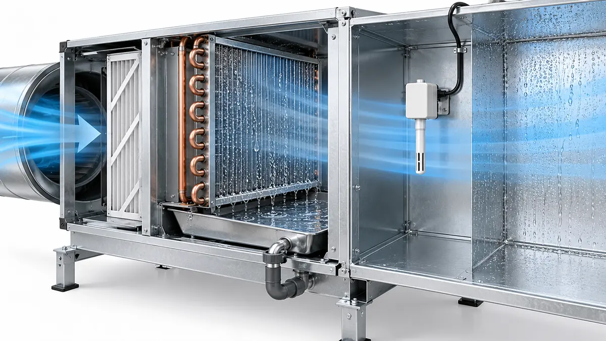
Condensation becomes a measurement problem when liquid water reaches a sensing element, inlet, filter, circuit board or cable entry that was meant to sample air rather than water. The useful first question is not “What is the room humidity?” but which surface became colder than the dew point of the air immediately around it? A cooling coil is supposed to collect and drain water during dehumidification. A duct humidity probe, gas detector or control module beside it may not be designed to get wet. Those two forms of moisture must be distinguished before a reading, alarm or failure is interpreted.
This guide is for people choosing, installing or troubleshooting HVAC sensors around cooling coils, outside-air sections, humidifiers, chilled beams and equipment cabinets. It explains how to separate air conditions from surface conditions and how to read a sensor's environmental specification. It does not make a generic sensor waterproof or set an installation position for every air handler. The final position and response to a wet safety device come from the actual instrument and equipment instructions.
Three different places can be “wet”
Intentional coil condensate. A cooling coil removes moisture because its cold surface contacts air whose dew point is higher than the coil surface temperature. Liquid water should collect on the coil and flow to a drain pan. In that part of the process, water is expected; a clogged drain or carryover into the downstream airstream is not. A sensor installed after the coil may encounter saturated air, droplets or splashing even if a sensor upstream sees ordinary relative humidity.
Unwanted wetting at the measurement point. A duct probe or gas-sensor inlet may see mist, a local cold surface or water trickling along the probe body. An RH element measures water vapor under its specified conditions; a water film on its protective cap is a different boundary condition. A temperature probe immersed in a drop can approach the water temperature rather than the intended air temperature. A gas inlet blocked by water can delay or prevent the target gas from reaching the sensing chamber.
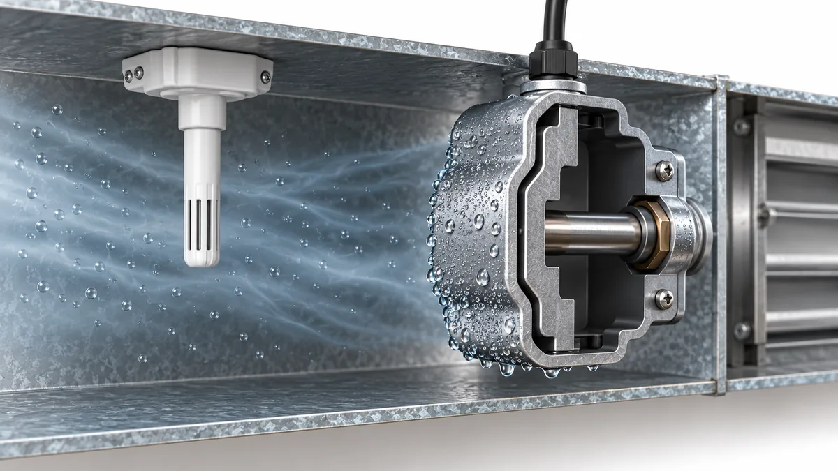
Condensation on the electronics or cable path. The air inside an enclosure, the duct outside it and the cable conduit can be at different temperatures. A cold metal wall or thermal bridge can collect water even when the probe tip remains dry. Water may then travel through an unsealed fitting toward a circuit board. A housing ingress rating, if one is provided, does not by itself prove that a gas inlet or RH element can operate while wet.
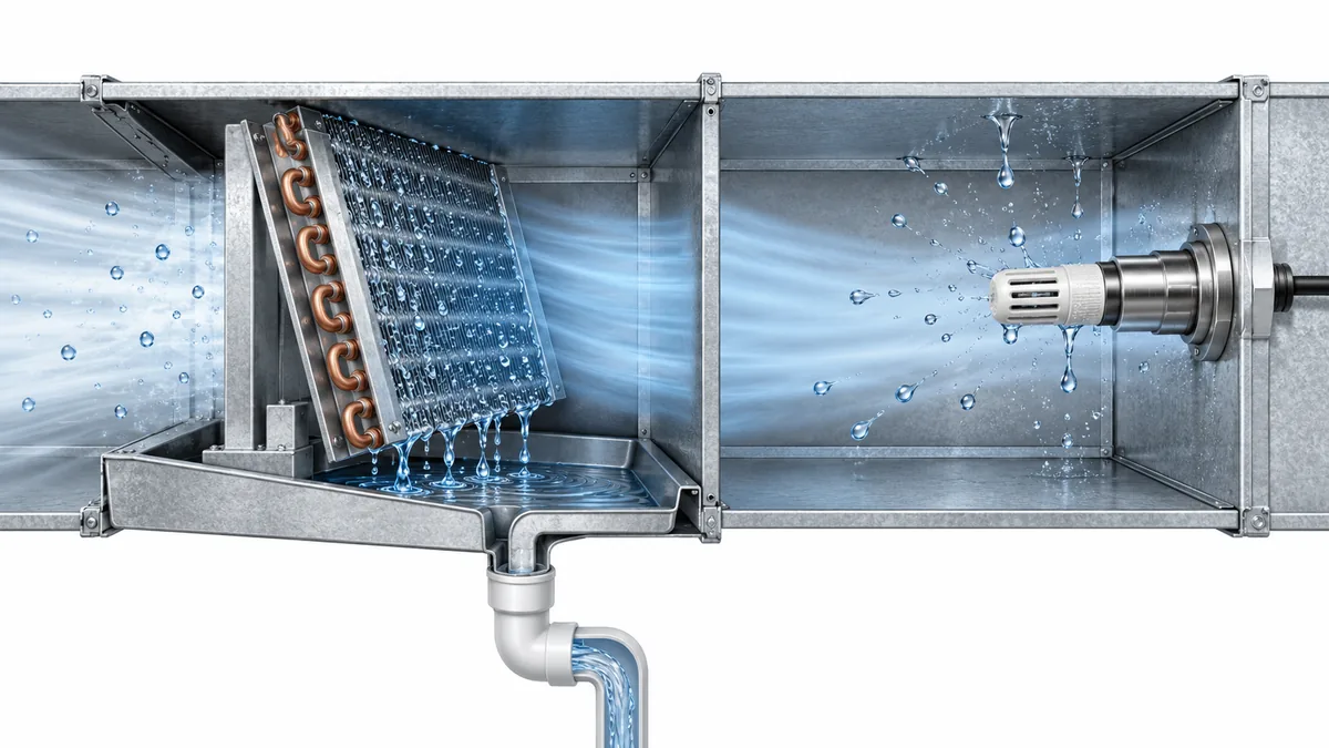
These cases lead to different fixes. Moving a humidity probe cannot repair a failed drain pan. Replacing a sensor cannot remove a persistent thermal bridge. Improving enclosure sealing cannot make a measurement representative if the probe is still in a spray plume. Identify the wet surface and the water path before choosing a remedy.
Dew point belongs to the local air, while condensation belongs to a surface
Relative humidity tells how close a parcel of air is to saturation at its present temperature. Dew point expresses the temperature at which that air would reach saturation if cooled without changing its water content. Condensation begins at a surface when the surface is sufficiently cold relative to the dew point of the air touching it. The surface may be the coil, a pipe, a probe stem, a duct wall or an electronics enclosure. The relevant temperature is surface temperature, not just the display value from a wall thermostat.
For example, an air handler may draw humid outdoor air past a cold duct penetration. The average return-air RH can be moderate while the metal around the penetration is below the local dew point. Conversely, air immediately leaving a wet cooling coil can be close to saturation while a warm transmitter head outside the insulated duct stays dry. Neither observation contradicts the other. It describes two different air-and-surface pairs.
Honeywell's humidity sensor theory guide explains that condensation depends on the active sensor surface relative to the surrounding gas dew point, and that water can evaporate slowly from a wetted element. An RH trace that rises rapidly and recovers slowly after a cooling or humidification event may therefore reflect local wetting. It could also reflect a genuine air-moisture change, a dirty filter, or controller smoothing. The shape alone is not a diagnosis.
The most useful comparison records air temperature and RH at the intended sampling point, an independent estimate of local dew point, and the temperature of the suspected cold surface. If the air is stratified or the surface is intermittently cooled, one average value will hide the critical period. Log the fan, coil, humidifier and defrost states at the same time. Avoid presenting a calculated dew point as a directly measured surface temperature.
Choose a location for the variable you actually need
An HVAC system contains several valid but different air samples. Outdoor intake air describes the weather-side load. Return air reflects a mixture from occupied spaces. Air immediately downstream of a cooling coil describes a cold and potentially wet process state. Supply air farther downstream may be warmer, better mixed and more suitable for a control sensor. A pipe surface or chilled panel has yet another job: warning about condensation on that surface.
| Intended decision | Useful measurement point | Moisture issue to check | Common misreading |
|---|---|---|---|
| Control room comfort or ventilation | Representative return or occupied-zone air | Wall effects, stratification, local heat and moisture sources | Treating one return-duct RH as every room's RH |
| Measure coil dehumidification | Before and after coil with suitable temperature/moisture instrumentation | Saturated discharge air, entrained droplets, drain carryover | Assuming every downstream RH probe can tolerate droplets |
| Control a duct humidifier | Location with adequately mixed water vapor | Mist or unabsorbed steam reaching a probe | Treating a local high-limit signal as average duct humidity |
| Prevent chilled-surface condensation | Surface sensor or air dew-point estimate paired with surface temperature | Thermal contact, changing room air, cable thermal bridges | Comparing room RH alone with a pipe temperature |
| Detect refrigerant or other gas near HVAC equipment | Manufacturer-approved gas detector position and inlet | Water or dirt at inlet, airflow changes, enclosure condensation | Calling an implausible gas signal a leak or a false alarm without checking the inlet |
Các Munters Dehumidification Handbook distinguishes the very wet air immediately following a condensing coil from other HVAC sampling points. A probe selected for ordinary mixed air should not be moved into a droplet-laden coil discharge simply because that location is convenient. Likewise, a sensor placed after a humidifier needs enough mixing distance for the actual device and duct geometry. Johnson Controls' HE-69xx0NP installation guide gives a model-specific location and condensation warning; its dimensions and distances are not a universal rule for all probes.
Before accepting a location, ask what the controller will do with the value. If an RH sensor controls dehumidification, does it represent the room, the return mixture or the cold coil discharge? If a temperature probe controls a freeze-protection sequence, is it on the intended section of coil or in a warm bypass stream? If a gas detector is safety-related, use its equipment's approved position and service instructions rather than applying humidity-sensor placement advice to it.
What wetting can do to different sensor types
The outcome depends on the sensing principle, package and exposure. It is not technically sound to say that “humidity sensors fail in water” or that “optical sensors ignore humidity.” Water vapor, liquid droplets and water on an optical surface are distinct challenges.
Capacitive RH elements commonly respond to water vapor through a moisture-sensitive film. If the protective cap or active region becomes wet, the displayed value may remain near saturation and recovery may lag after the air dries. The element may recover when the film dries, but contamination deposited during wetting can affect later behavior. Honeywell's theory guide describes the importance of wetting and drying dynamics; the decision to reuse a particular assembly belongs to its manufacturer instructions and a subsequent check.
Air-temperature probes can measure a local temperature accurately yet answer the wrong question if a drop, cold mounting bracket or radiatively cold wall dominates their thermal contact. A sensor may be electrically healthy while biased by installation. The difference between air temperature and surface temperature is especially important for dew-point control. A surface thermistor must be attached to the surface it is meant to follow; an air probe should not be treated as a pipe sensor because it sits nearby.
Gas detectors have inlets, diffusion barriers, filters and sometimes optical paths. Liquid water can obstruct diffusion or change a sample path. A wet module can also create electrical faults or unreliable readings. The response varies by design; do not assign a universal direction of error. If a safety-related detector becomes wet or signals a fault, follow the equipment's prescribed fault procedure rather than declaring the atmosphere safe from one displayed number. For broader humidity mechanisms, see our gas-sensor humidity guide.
Optical and particle devices may be affected by droplets, fog or condensation on optical surfaces, but their interpretation depends on the instrument and measurement target. A PM sensor may count hygroscopic growth or droplets as particles, while an NDIR gas module may face moisture effects through an optical path or inlet. Those are not interchangeable mechanisms. An instrument's humidity compensation may address a characterized vapor effect without making liquid-water exposure acceptable.
Read each data sheet for operating RH, whether condensation is excluded, inlet protection, recovery instructions and the specific temperature range over which performance is stated. For example, the Winsen ZRT512E refrigerant module page lists its own working RH range with a “No condensation” qualification. That wording matters more to a wet-cabinet decision than an impressive upper RH number alone. It does not establish that another model has the same limit.
Thermal bridges and mounting geometry can create a local wet spot
A duct probe crosses a boundary between duct air and ambient plant-room or attic air. Its metal stem, mounting plate, fasteners and cable can conduct heat across that boundary. A cold stem may be below the surrounding air's dew point even if the main duct is insulated. A warm transmitter head can also heat the probe or temperature element. Vaisala's duct-installation guidance emphasizes mounting the head within the insulation envelope and preventing heat transfer that leads to condensation and incorrect readings.
Orientation determines where any water can flow. A downward-pointing probe may lead droplets toward the sensing element or cable entry in some designs; another probe may explicitly prohibit a different orientation. Follow the manufacturer's permitted positions and mounting drawing. Do not turn one supplier's orientation advice into a rule for every sensor. A mounting flange can also channel wash water or condensate around a gasket. Inspect the assembled cable gland and conduit path, not only the sensing tip.
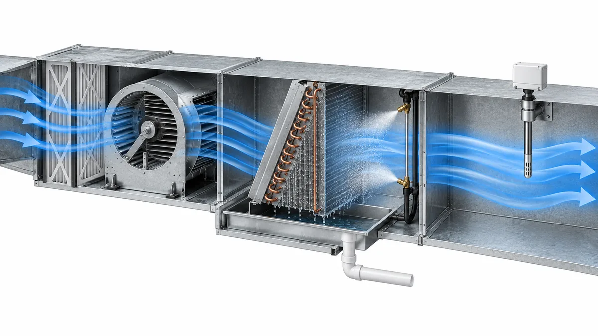
Airflow changes across operating modes. A sensor that stays dry with the fan on may see cold, still air after shutdown. Defrost, outside-air economizer operation, humidifier cycling and low-load cooling can all move the dew-point and surface-temperature relationship. The location review should include those modes that the equipment actually uses. A single snapshot under steady full-load operation is not enough to prove that the probe will never be wetted.
A practical diagnosis starts with a timeline, not a replacement part
When a reading becomes implausible after cooling or humidification starts, preserve the controller trend before resetting or replacing anything. Record the sensor's raw value if available, engineering units, timestamp, fan state, coil valve or compressor state, humidifier command, outdoor and return-air conditions, and any device fault flag. If the controller filters or averages the signal, note the update period. A delayed display can come from software as well as from a wet cap.
Then compare three observations: the intended air sample, the suspect sensor's physical condition, and a suitable independent reference. A handheld meter placed elsewhere in the duct does not automatically invalidate the fixed sensor; it may be sampling a different air stream. Put the reference where it reasonably samples the same mixed air, using the reference instrument's own settling time and humidity limits. If the suspect probe is near a drain leak or humidifier plume, photograph the water path and record the operating mode rather than relying on one RH reading.
The following sequence separates the most common explanations without requiring a made-up test gas or unsafe bypass:
- Identify the measurement task. Confirm the intended location and model from the equipment drawing and sensor manual.
- Inspect water routes. Look at coil carryover, drain pan, spray source, cold stem, insulation gap, cable entry and enclosure. Do not open energized safety equipment contrary to its service instructions.
- Compare local conditions. Record air temperature/RH and likely cold-surface temperature, with uncertainty and sensor placement documented.
- Check the signal path. Distinguish a true sensor output from an analog scaling error, stale digital value, wiring fault or controller substitution.
- Observe recovery or prescribed service. Follow the manufacturer-approved drying, inspection, replacement and functional-check instructions. A return to a plausible number alone is not proof of qualified performance.

If the same event recurs, redesign the measurement location or water-management path rather than repeatedly replacing a sensor. A new device in the same wet location can show the same symptom. If the sensor participates in an alarm or protection function, maintain the required safe state while its condition is investigated; a building-automation trend is not authorization to defeat that function.
Read environmental specifications as separate promises
An instrument data sheet may contain an operating temperature range, an RH range, an ingress rating, an accuracy statement, a response-time test and a storage limit. Each can be true under different conditions. A device that survives storage in a damp package is not necessarily specified to measure accurately while condensed water covers its inlet. An enclosure IP rating may protect electronics but leave the exposed sensing tip subject to a stricter condition.
For a specification review, write down the exact model and revision, then answer these questions:
| Câu hỏi | Evidence to locate | Why it changes the decision |
|---|---|---|
| Is liquid condensation allowed during measurement? | Explicit noncondensing/condensing language, not just maximum RH | Water vapor limits cannot be used as droplet tolerance |
| Which part is rated? | Element, probe, transmitter head, cable and inlet drawing | An enclosure rating may not cover the exposed sensor |
| What are the accuracy test conditions? | Temperature, RH, airflow, pressure and stabilization | A room-temperature accuracy number may not apply after cold start |
| What happens after wetting? | Recovery, cleaning, recheck or replacement instruction | Plausible output after drying may still need verification |
| How is failure signaled? | Fault bit, analog out-of-range behavior or relay state | The controller must not interpret a fault as clean air |
| How is it installed? | Approved orientation, insertion length, insulation and service access | Geometry determines both sample and water path |
A useful purchasing requirement is not “waterproof sensor.” It is a defined task and environment: what air or surface is measured, likely spray and condensation exposure, required accuracy and response, permitted mounting, and the action on failure. A supplier can then provide a model-specific data sheet and installation guide. Where a location is unavoidably wet, a sensor intended for that environment and measurement task may be necessary; a generic duct RH probe should not be assumed adequate.
Compare the symptom with the water path
An efficient site visit begins with a sketch of the air handler and its thermal boundaries. Mark the outside-air intake, mixing section, filter, coil, drain pan, humidifier, supply duct and each sensor. Then mark which surfaces are insulated and which penetrations connect warm and cold spaces. This simple drawing can reveal that a transmitter head is in a warm plant room while its metal probe stem crosses a cold duct wall, or that a cable conduit is carrying humid air toward a colder enclosure. Those details may be invisible in a building-management trend.
Next compare independent observations, not just two numbers from the same controller. A room RH sensor may show a normal average while a duct probe is repeatedly wetted by local droplets. A handheld humidity instrument used briefly at the same point can help distinguish a local air condition from a failed permanent element, but only if the instruments are allowed to equilibrate and their own temperature and accuracy limits are respected. A contact measurement of the suspicious surface and an estimate of the nearby air's dew point can clarify whether condensation was physically plausible. Neither reading should be represented as a laboratory validation unless it was taken and documented under an appropriate method.
The symptom's timing can narrow the search. If an RH signal sticks near saturation only during cooling and slowly recovers after the coil is off, inspect the downstream wet-air path, drain and sensor cap. If the instrument faults after the enclosure is cold-soaked and then returns as the room warms, inspect the electronics housing, cable entry and thermal bridges. If multiple sensors change at the same moment, check a real process event or shared control/power problem before replacing all of them. These are investigation cues, not proof of a specific failure mode.
Document what was actually found: droplets on a probe, a wet cable gland, a blocked drain, an intact but poorly located sensor, or no visible moisture. Record the operating mode, air and surface conditions, sensor status, photographs and the applicable manual revision. A repaired drain may stop new carryover but cannot automatically restore a contaminated RH element. Conversely, a new transmitter may work on the bench and repeat the same failure when installed at the original cold penetration. The final check should confirm both the water path and the measurement task under representative operating modes.
Câu hỏi thường gặp
Can a duct RH sensor show 100% even when the room is not that humid?
Yes. The duct location may be colder, saturated or wetted while occupied-zone air is different. The sensor may also retain water on its cap and recover slowly. Compare a suitable reference at the same sampling location and inspect the physical condition before deciding whether the room or sensor is wrong.
Is condensation behind a cooling coil always a defect?
Water on the coil and in its drain system is an expected part of dehumidification. Droplets carried into a measurement probe, leaks from the pan or moisture reaching electronics are different conditions. Document where the water is found and whether it follows the designed drain path.
Does temperature compensation prevent condensation errors?
No. Compensation can correct a characterized temperature dependence of a sensor under specified conditions. It does not remove a water film, open a blocked gas inlet or seal a cable gland. Check the actual module's environmental qualifications.
Can I use an RH reading to decide whether a pipe will sweat?
Only with the corresponding air temperature, a defensible dew-point calculation and the pipe-surface temperature at the location of concern. The surface may be colder than the air; one room RH number alone is insufficient. Follow the chilled-surface control design for the installed equipment.
When may a wetted sensor return to service?
That depends on its construction, exposure and manufacturer instructions. Record the event and any required drying, inspection, replacement or functional check. For a safety-related detector, an apparently normal display after wetting does not by itself requalify the device.
Nguồn kỹ thuật
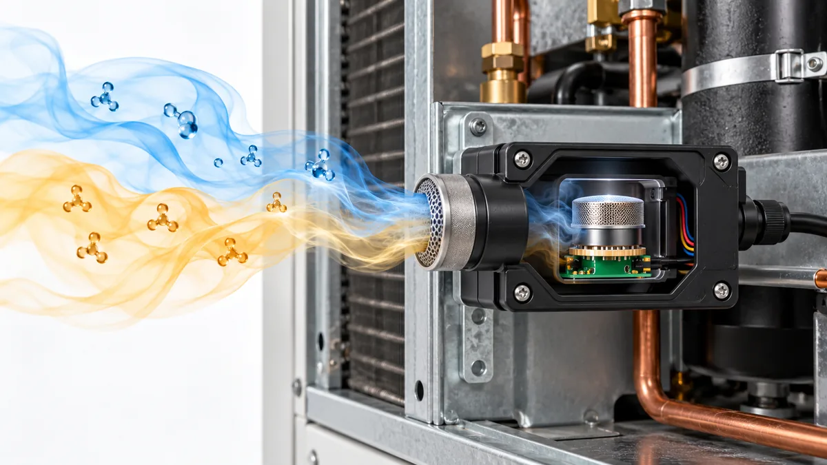
Một loại khí khác có thể kích hoạt máy dò chất làm lạnh không? Đọc các tuyên bố về độ nhạy cảm chéo
Understand refrigerant-detector cross-sensitivity, compare NDIR and MOS evidence, and read gas-interference claims without dismissing a real alarm.
Đọc thêm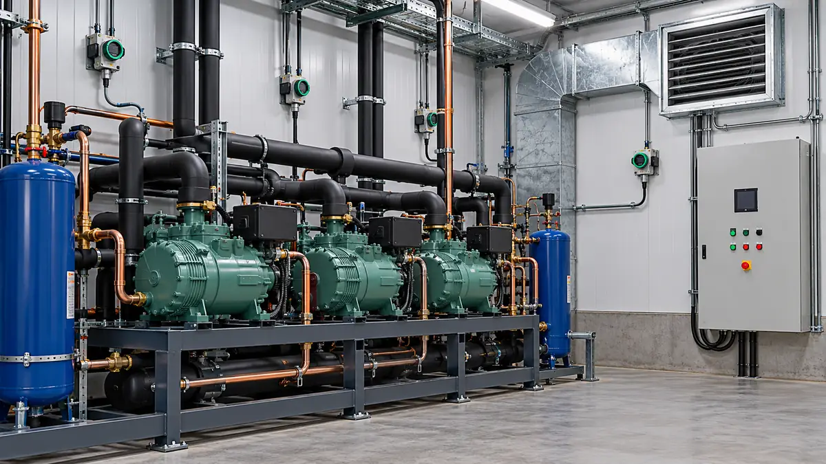
Nhật ký giám sát khí trong phòng làm lạnh nên ghi lại những gì?
Build a useful plant-room gas log by recording detector identity, configuration, alarms, faults, ventilation response and maintenance evidence.
Đọc thêm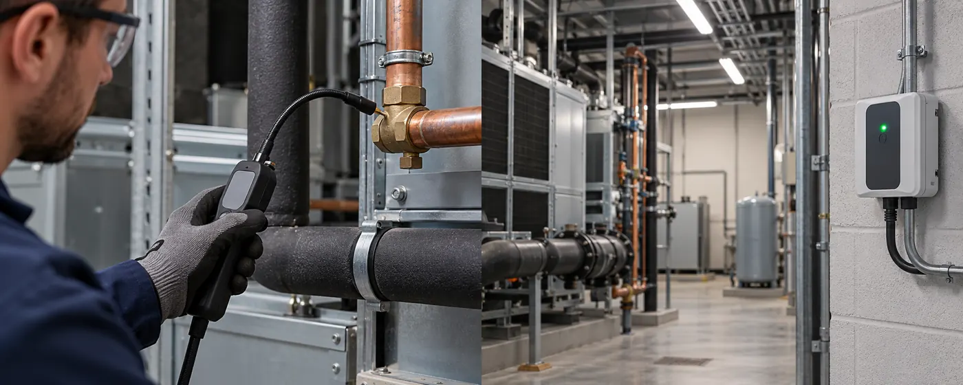
Phát hiện chất làm lạnh di động và cố định: Công việc của chúng khác nhau như thế nào
So sánh thiết bị định vị rò rỉ cầm tay, thiết bị giám sát điểm cố định và hệ thống hút theo vị trí mẫu, chuỗi phản hồi và nhu cầu vận hành thử.
Đọc thêm
Nhận dạng chất làm lạnh và đo nồng độ: Bạn cần thử nghiệm nào?
Phân biệt thiết bị nhận dạng điện tích kín với giám sát nồng độ môi trường xung quanh, vị trí rò rỉ cầm tay và kiểm tra độ tinh khiết của chất làm lạnh chính thức.
Đọc thêm
Độ ẩm ảnh hưởng như thế nào đến kết quả đọc của cảm biến quang học PM2.5
Tìm hiểu lý do tại sao độ ẩm, khả năng hấp thụ nước, sương mù và sự ngưng tụ có thể ảnh hưởng đến ước tính PM2.5 quang học cũng như cách điều tra và xác nhận mức tăng đột biến của không khí ẩm.
Đọc thêm
Cách giải thích kết quả đo CO2 trong cabin xe
Đọc xu hướng CO2 trong cabin xe cùng với hành khách, chế độ HVAC và điều kiện tuyến đường, đồng thời tách các manh mối thông gió khỏi các câu hỏi về an toàn hạt và khí thải.
Đọc thêm