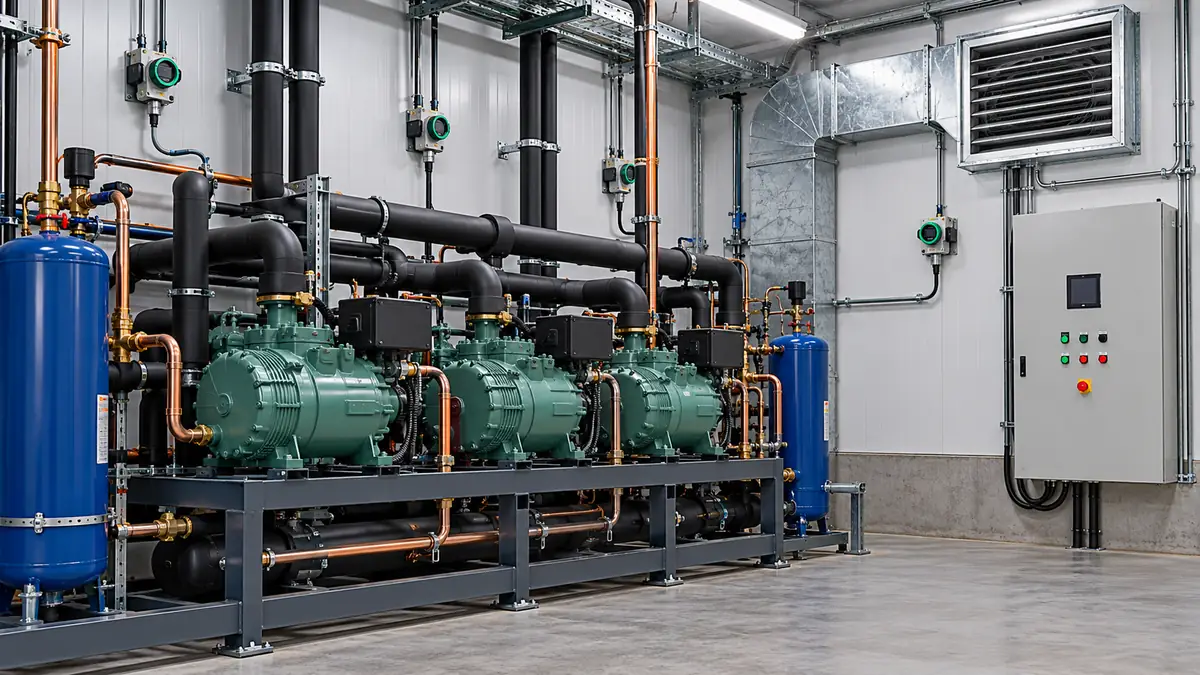
An A2L refrigerant detector cannot be evaluated from one attractive specification line. First identify the exact refrigerant and appliance, then follow the evidence from the sensing component through the assembled refrigerant detection system (RDS), the appliance evaluation, and the installation instructions for that particular unit. A sensor data sheet may describe a detectable gas and an electrical output; it does not, by itself, establish where the sensor must be mounted or what the finished air conditioner will do during a leak or a sensor fault.
This distinction matters most when several suppliers contribute to one installation. The sensing element may come from one company, the controller from another, and the air handler from a third. Their documents answer different questions. A purchaser who reads “UL 60335-2-40” on a sensor leaflet and assumes that every combination of controller, wiring, orientation and appliance is approved has skipped the very interfaces that determine whether a detection signal produces the intended mitigation. Intertek's explanation of RDS evaluation explicitly separates a recognized sensor from evaluation of the complete RDS and its use in an appliance.
Start with the exact application, not the word “A2L”
A2L is a refrigerant safety classification, not a detector calibration or a universal alarm setting. Begin a review record with the appliance manufacturer and full model number, the refrigerant named on its marking, the applicable market, the installation configuration and the document revision supplied with that equipment. Record whether you are reviewing an integral detector inside an HVAC appliance, a room monitor, or a portable service instrument. Those are different measurement jobs; our refrigerant sensor task guide compares them.
Next, identify the exact gas or blend. A sheet that lists R-32 is not automatically a specification for R-454B, even if both are A2L. Some products support several named refrigerants, but their thresholds, calibration modes or stated performance may differ. The PENN GM200 technical specifications, for example, direct the reader to ordering information for the target refrigerant; the model family name alone is insufficient. A model that is intended for R-454B and R-32 may still require a specific configuration, part number or controller setup. The correct source is the current documentation for the exact combination being installed.
Regional and edition references also matter. UL 60335-2-40 concerns particular heat pumps, air conditioners and dehumidifiers, whereas commercial refrigeration may involve a different appliance standard. A certification or test claim has to be read within the scope printed on the report, component file or equipment marking. UL Solutions' discussion of fourth-edition refrigerant detection requirements is useful background for North American applications, but the applicable edition, amendments and local adoption still need checking for the project. A web summary cannot replace the current standard text, product listing and authority's requirements.
There is no benefit in turning this check into a general refrigerant chemistry essay. The practical question is narrower: does this exact hardware and documentation chain correspond to the exact refrigerant, appliance and installed arrangement in front of us? A reliable answer starts with a matching identity on every document. If the equipment nameplate says one refrigerant while the sensor or controller instructions identify another, stop the document review and obtain an OEM resolution rather than assuming the gases are interchangeable.
Put five documents in the right order
The following reading order prevents a component claim from being mistaken for a finished-system claim. Some manufacturers combine several items in one manual; what matters is that each question has an identifiable answer.
| Document or record | The question it should answer | What it does not establish by itself |
|---|---|---|
| Appliance marking and installation manual | Which refrigerant, model, orientation, sensor position, wiring and mitigation arrangement were specified for the finished appliance? | Whether a replacement part with a similar name is automatically acceptable. |
| Sensor/module data sheet | Which gas, range, output, electrical supply, environment and response conditions apply to the stated module? | Complete controller logic or installed appliance performance. |
| Component certification or recognition record | Which component and revision were assessed, under what scope and conditions of acceptability? | Approval of every later assembly or installation. |
| RDS controller/interface documentation | How are sensor signals, faults, power and mitigation commands interpreted by the assembly? | The air path and physical mounting requirements of every appliance. |
| Commissioning and service instructions | How should this particular product be inspected and its prescribed functions checked and maintained? | Permission to substitute an improvised gas-release test or bypass a fault. |
Read the appliance manual and marking first because they define the target system. Then use the sensor sheet to verify that the installed part is the specified part, the RDS/controller documents to trace the electrical and logical chain, and the recognition or listing information to check the precise assessment scope. Finally, use the service instructions to understand how the manufacturer expects the installed function to be verified and maintained. This is a reading sequence, not a claim that every jurisdiction requires exactly five separately bound documents.
For a prospective component purchase, the sequence works in reverse after the intended appliance is known. Write the requirement from the equipment design, compare candidate module data and certification scope, and ask the OEM or certification body how the assembled RDS will be evaluated. A broad “A2L compatible” claim is a starting filter, not a completed acceptance decision.
Read a sensor specification as a measurement contract
Several terms that look similar describe different things. 目標氣體 states what the product is intended to respond to. 測量範圍 is the span of reported concentration or signal. Detection threshold is the condition at which the device is intended to indicate a specified state. 準確性 describes error under stated test conditions; it is not the same as threshold. 回應時間 describes a time criterion under a defined exposure and state. Output type specifies what information the controller actually receives. Check every qualifier beside each number.
Many A2L safety documents use a percentage of the refrigerant's lower flammability limit (%LFL). That is not the same unit as parts per million. A value such as 25% LFL is relative to a particular refrigerant's LFL, not a universal ppm concentration for all A2L gases. It should not be copied from one gas to another without the relevant refrigerant properties and product configuration. A controller receiving a binary contact may not know the continuous concentration at all. A module with a digital concentration output still needs the receiving controller's logic and failure handling to be understood.
As an illustration of how much context a real specification can carry, the GM200 sheet identifies named refrigerants, supply voltage, environmental limits, sampling, compensation and recognized standards, while distinguishing some manufacturer claims from properties evaluated by UL. Those details belong to that family and revision. A different module, such as the Winsen ZRT512E refrigerant sensor, must be read against its own listed gases, measuring span, electrical interface and documentation. Neither example can supply missing specifications for the other.
Do not read an operating temperature range as a promise of identical threshold accuracy or response time at every temperature. Look for the conditions under which accuracy and response were characterized, and whether humidity, condensation, pressure or warm-up change the result. If a data sheet gives an “operating” range and a narrower tested or compensated range, the narrower performance statement controls the specific claim. Texas Instruments' A2L application brief describes multiple sensing approaches and their trade-offs; it is a useful reminder to evaluate the complete performance condition rather than rank technologies by a single headline number.
The lifetime line also deserves context. Determine whether it is a rated service life, an expected design life, a warranty period, or a condition checked as part of a certification. Find the corresponding self-test, fault and replacement instructions. Do not infer that “no field calibration” means “no inspection, no functional check, and no eventual replacement.” A sealed component may have a manufacturer-prescribed service process even when adjustment of its threshold is not permitted.
Separate the test-gas step from the installed leak scenario
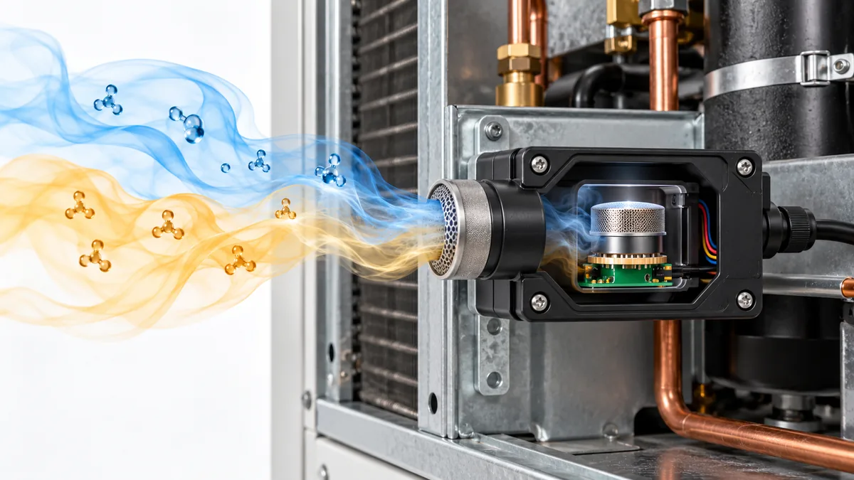
A laboratory response statement is usually made under a defined gas exposure: concentration, temperature, humidity, airflow and start condition. An installed release adds transport time from the leak to the sensing inlet. The gas may be diluted by the fan or delayed by a compartment. Compare like with like: a sensor's response after gas reaches its inlet, an RDS's response after the specified test exposure, and the appliance's total mitigation behavior are three different clocks. A short sensor time cannot be added to an unverified installation and presented as proof of an equally short room-wide warning time.
Also inspect the meaning of a threshold tolerance. If a data sheet quotes accuracy around a detection threshold, determine whether the figure is in percentage points of LFL or a percentage of the indicated reading. Those are not equivalent. Look for the test gas named in that row, the calibration state, the temperature/humidity range, and whether the value is typical, minimum, maximum or part of a certification criterion. If the document offers a graph but no numerical guarantee in the environmental corner relevant to the appliance, ask the manufacturer which statement governs. This is more useful than calculating an alarm concentration from a headline range alone.
Finally, distinguish the threshold at which a module changes state from the concentration at which the complete system is required to act under the applicable assessment. The OEM may deliberately use a lower trigger, multiple sensors or a conservative controller design. The exact design must be documented, not inferred by treating the standard's evaluation point as a user-adjustable alarm setting. Record the gas, condition and assessed object beside every numeric claim in the review table.
Follow the signal all the way to mitigation
An RDS is more than a sensor. A useful document review traces a complete event: refrigerant reaches the sensing location; the module changes its output; the controller interprets that output; the appliance enters the specified mitigation state; operators can identify the event and restore service according to the manufacturer. A separate path traces a fault, disconnected sensor or loss of power. Each step can fail even when the sensing element itself functions.
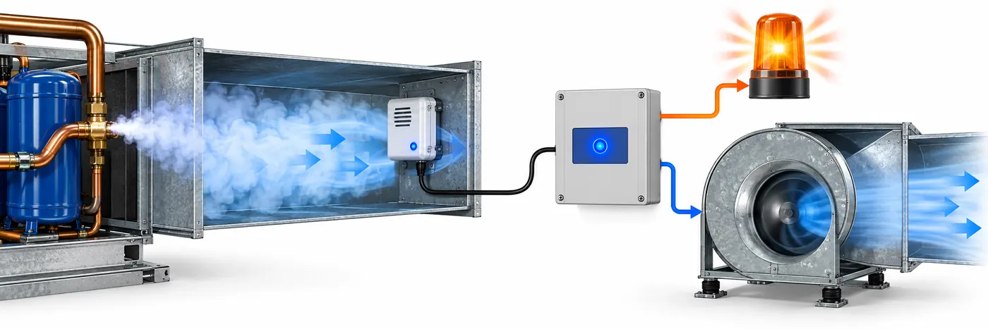
UL's HVAC inspection guidance defines an integral RDS as one or more stationary sensors that initiate automatic mitigating action when required by the equipment's certification. It tells inspectors to verify the manufacturer-specified sensor positions and wiring. The same source notes that configurations with different equipment orientations may require different sensor positions. That makes the installation drawing a performance-relevant document, not a cosmetic accessory.
At the interface, record the connector and pinout or terminal designations, supply voltage and allowable wiring conditions. Ask whether a normal-state signal, alarm-state signal and fault state are distinct, and how the controller treats an open circuit or communication loss. If a digital bus is involved, identify the supported protocol and register or message semantics; if a dry contact is involved, identify the normal and alarm states. The controller document should identify which actions happen on a detected event and which happen on a fault. Merely proving that a display changes color says little about fan operation, shutdown, annunciation or recovery.
One manufacturer example shows why the division matters. The YORK A2L sensor installation detail documents sensor LEDs, mounting, wiring and a connection to an A2L control box, while expressly allocating controller programming, testing and mitigation responsibility to others for that configuration. Reading only its sensor table would leave the response chain unresolved. Another product may allocate those responsibilities differently. The key is to locate the boundary in the actual documents.
Claims about elapsed response require equally careful reading. A module response-time value may start when test gas reaches the sensor under specified conditions. The appliance-level mitigation time may include sensor response, communication, controller logic and actuator response. UL's standards analysis discusses a system response at a specified fraction of LFL in its North American context. It does not justify applying one timing number to every device or to an untested combination. If a tender specifies a required total response, ask for evidence for the complete path and its test conditions.
Recognized component, evaluated RDS and listed appliance are separate scopes
Certification vocabulary is easy to compress into one ambiguous word: “certified.” Keep the object of the assessment attached to the claim. Was the sensing component recognized? Was a controller-plus-sensor RDS evaluated? Was the finished appliance listed with that exact RDS? Intertek's RDS guidance explains that a recognized sensor can be used in an RDS evaluation, but the assembled RDS still needs assessment of system behavior. An already evaluated RDS also has conditions of acceptability when incorporated into an appliance.
Ask for the certification file or product record, product identifier, standard and edition, report date or revision, and any conditions of acceptability relevant to the design. Check that the product label and order code match that record. If the record applies only to a sensor board under a given enclosure or controller condition, a visually similar replacement in a different assembly has not inherited the whole-system claim. A seller's phrase “designed to meet” is a design intention unless supported by the precise assessment record claimed.
The standard on a leaflet may have been revised or supplemented by a Certification Requirement Decision. UL Solutions describes how fourth-edition treatment of response, drift, environment and other conditions evolved through CRDs. For procurement or inspection, the useful action is to record the exact cited document version and compare it with the version used in the product assessment and the project requirements. Do not infer that a marketing page mentioning a current standard automatically updates an older certification file.
This scope discipline protects both engineering and communication. In an article or catalog, “this module is intended for R-32 and R-454B detection” is a module statement. “This RDS initiates a particular mitigation sequence under defined tests” is an assembly statement. “This heat pump is listed with this RDS when installed as directed” is an appliance statement. They need different evidence. Keeping the nouns attached to the claims prevents accidental overstatement.
Installation details can change the effective sample
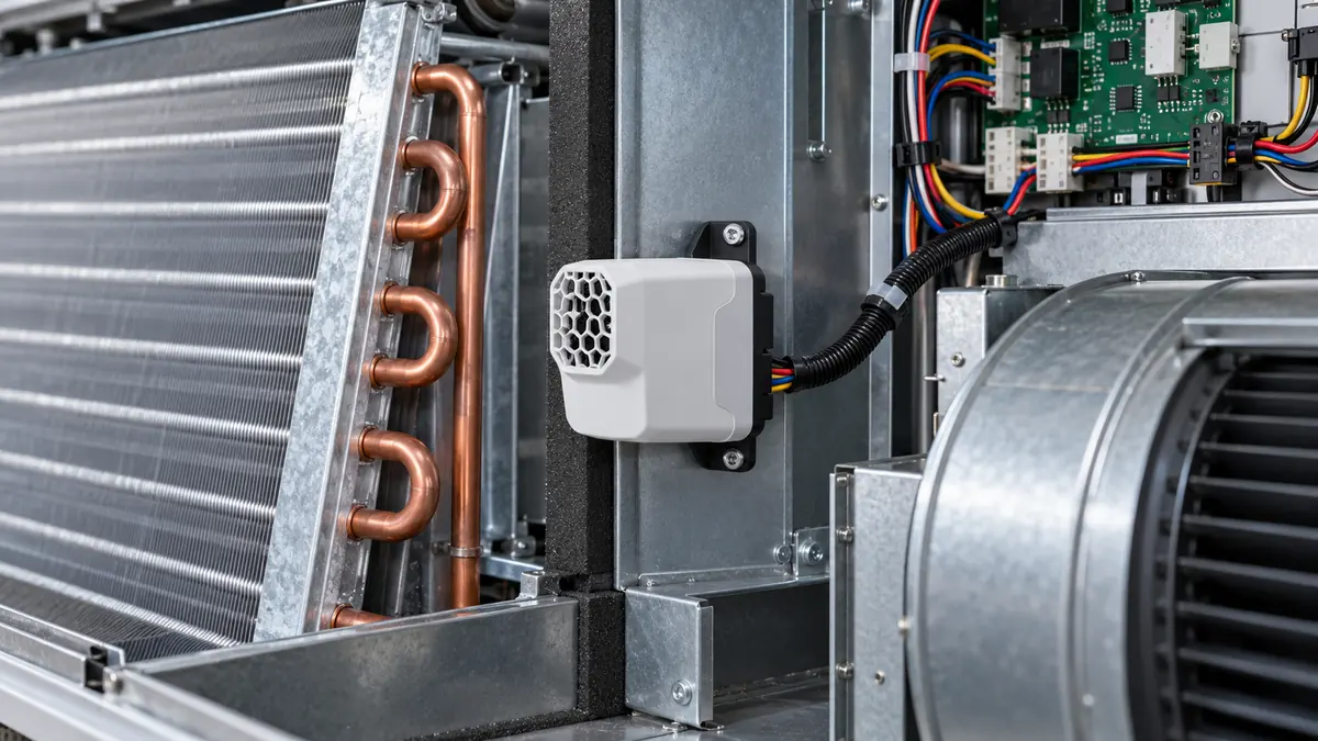
A stationary detector measures air at its sensing opening, not a theoretical room average or every point within an enclosure. The appliance manual should show permitted mounting positions, orientation, cable route, connector protection and any multiple-sensor arrangement. A coil, drain pan, fan compartment or field-convertible cabinet can change where leaked refrigerant first travels and how air is mixed. UL's inspection article specifically directs readers to the OEM instructions when orientation changes the sensor location. Do not replace that drawing with a generic rule such as “install every A2L detector near the floor.”
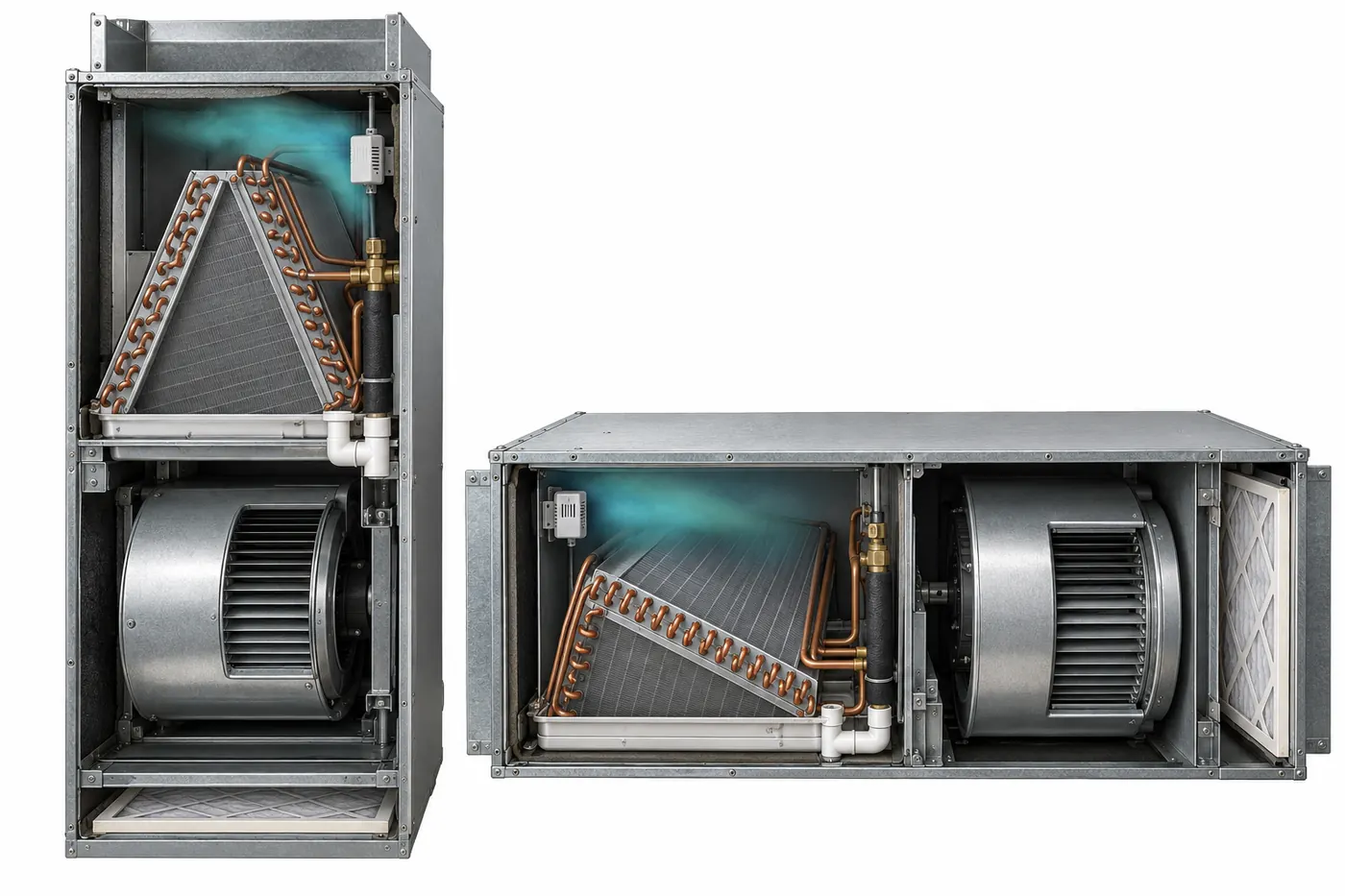
Environmental statements should be read at the location of the sensing element. A unit may experience cold air, coil condensation, wet cleaning, vibration, electrical noise and periods without airflow. Read the manufacturer's temperature and humidity range, enclosure or ingress statement, condensation restrictions, and cleaning/service instructions together. A wide nominal range does not override an exclusion such as noncondensing humidity or a connector orientation requirement. The YORK example provides a concrete instruction about acceptable mounting orientation and connector direction; that is an example to illustrate what a real manual can specify, not an instruction for unrelated equipment.
Maintenance also belongs to the installed system. Identify the allowed self-test and functional-check procedure, the meaning of each indicator, how faults are logged, how a sensor is replaced and how the assembly returns to normal operation. Do not improvise by spraying refrigerant into a cabinet, forcing an alarm through a relay bypass, or suppressing a fault to keep cooling running. Qualified personnel should follow the exact OEM instructions and applicable site procedures. A useful editorial question is whether the documents make these actions traceable; their absence is a request for clarification before acceptance.
A document-review example without assuming performance
Suppose a heat-pump submittal calls its unit “A2L-ready.” The equipment marking specifies R-454B, but a proposed spare sensor's web page prominently says “A2L” and its detailed ordering table lists only R-32 for the chosen part number. The controller sheet shows a binary input, while the sensor sheet describes a digital bus. The appliance manual specifies a sensor position for vertical airflow, but the project drawing uses a horizontal cabinet arrangement.
None of these mismatches proves that the design is unsafe; it proves that the submitted documents do not yet establish the intended chain. The reviewer should ask for the exact approved sensor part number for R-454B, the interface or compatible controller assembly, and the appliance installation instructions for the horizontal configuration. If a substitution is proposed, obtain the OEM's acceptance and the applicable evaluation record. A promised future field adjustment is not a substitute for evidence that the part and system were designed and assessed for the required use.
This exercise also shows why a fast search for “A2L sensor” is only the first step. Search results can reveal candidates and questions, but the answer lives in matched product records, revisions and installation details. Treat unmatched fields as open questions rather than filling them with assumptions from another model.
A compact review record

For each actual appliance, keep a one-page record with the following fields. It makes later replacement or audit work easier because it preserves the basis of the decision.
| Record item | Evidence to capture | Common ambiguity to resolve |
|---|---|---|
| Equipment identity | Model, serial or configuration, refrigerant on marking, installation orientation | Brochure family name versus exact installed variant |
| Sensor identity | Part number, hardware/software revision, named refrigerant(s), data-sheet revision | Another gas or another output variant in the same family |
| RDS identity | Controller part/revision, sensor count, interface, fault and alarm logic | Sensor approval presented as complete-RDS approval |
| Assessment scope | Listing/recognition file, standard and edition, conditions of acceptability | “Compliant” without an identifiable assessed object |
| Physical installation | OEM drawing, sensor position, wiring route, environmental limits | Generic mounting recommendation replacing OEM drawing |
| Functional verification | OEM procedure and record for normal, alarm and fault paths | Visual indicator check mistaken for complete mitigation test |
| Service ownership | Replacement parts and service method, who can reset or modify settings | An unapproved substitution or unrecorded setting change |
The record should cite document titles and revisions rather than copying isolated numbers. If the manufacturer changes a sensor or controller revision, the reviewer can see which assumptions need rechecking. If a location changes after duct or cabinet modification, the record reveals why the sensor placement may need review. This is especially useful where the same module family appears in several appliance designs.
Questions readers often ask
If a sensor says it meets Annex LL, is the appliance compliant?
Not on that fact alone. Determine exactly what was assessed—the component, RDS or appliance—and read the conditions under which the assessment applies. The completed RDS and its integration into the appliance may require further evaluation. The equipment marking and installation instructions are essential for the actual unit.
Can I use an R-32 sensor for R-454B because both are A2L?
Only if the precise part number, configuration and evidence explicitly support R-454B in the intended system. A2L is a safety group, not a guarantee of identical sensor response. Check the named gas and the OEM-approved assembly before substitution.
Does “0–100% LFL” tell me the alarm threshold?
No. It describes a reported range for a particular product. Find the stated trigger or controller setting, its tolerance and test conditions, and the associated system response. In a binary-output system, the controller may receive only state information rather than a continuous concentration.
Does “no calibration required” mean no maintenance?
No. Read the OEM's self-test, inspection, fault, service-life and replacement instructions. “No field recalibration” describes one maintenance action; it does not remove the need to keep the installed response path functional.
Where should the detector be mounted?
Use the exact appliance's installation instructions and approved orientation. Airflow, coil arrangement and cabinet conversion can change the specified location. A generic density-based rule or a photograph from another model cannot replace the equipment drawing.
An A2L detection system is understandable when its documents tell one coherent story: the right gas is sensed at the specified location; the specified module and controller exchange a defined signal; a fault is handled; and the listed appliance responds as documented. If any link in that story is missing, the productive next step is to obtain the missing OEM or certification evidence—not to stretch a single sensor specification into a system-wide assurance.
技術來源
- UL Solutions: Updated Requirements for Refrigerant Detection Systems
- UL Solutions: Inspecting Refrigerant Detection Systems in HVAC Equipment
- Intertek: Refrigerant Leak Detection Systems
- PENN Controls: GM200 Series Technical Specifications
- YORK: A2L Gas Leak Detection Sensor Installation Details
- Texas Instruments: A2L Refrigerant Adoption—Considerations and Requirements