
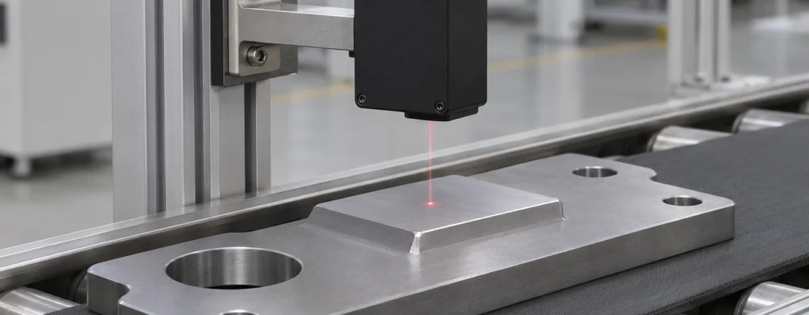
根据机器中必须测量的距离和表面选择激光三角测量位移传感器。建立零件基准,计算出最近和最远的可能目标位置,并检查激光束和返回接收器的激光束是否保持畅通。然后确保该点适合这些位置处的最小特征,并且控制器在该特征通过时接收到足够的有效样本。使用生产零件以预期速度对照独立参考确认组装测量结果。
在固定校准目标上重复几微米的传感器仍然可能会错过狭窄的台阶、跟随光泽反射或报告其自身安装支架的运动。有用的评估将光学返回、测量几何结构和控制器定时分开,以便可以在工作台或生产线上检测到每个故障。
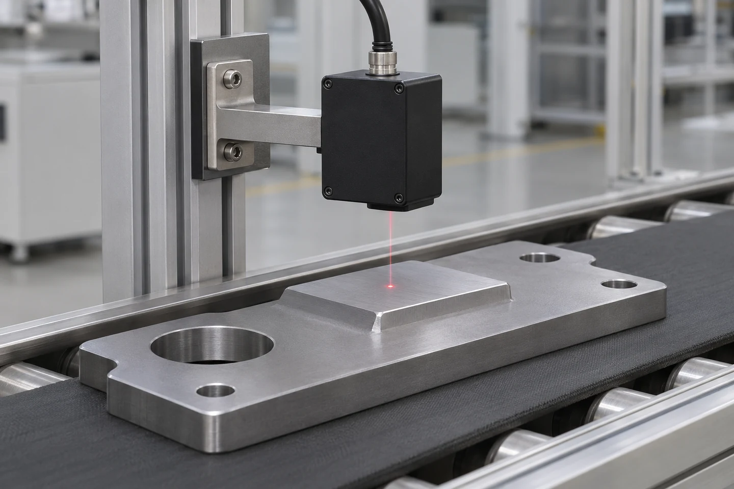
An overhead head observes one area of the passing part. The chosen datum and the controller's selection of samples determine what dimension the station reports.
定义测量和数据
A point triangulation head projects a spot on the target. A receiver lens, offset from the emitter, forms an image of returned light on a position-sensitive detector. A change in target distance moves that image on the detector. The head or its controller maps the detected image position to distance using its calibrated optical geometry. The return has to reach the receiver with a shape and intensity the sensor can interpret. The manufacturer's explanation shows how detector position, optical angle and usable span relate. Vitrek 激光三角测量原理
Distinguish the head's distance reading from the dimension the machine needs. For an overhead head with a vertical beam, the top moving up makes the gap smaller. If the control screen defines upward displacement as positive, compute 参考间隙减去当前间隙。对于高于固定机器基准的高度,参考间隙是相同几何形状中与该基准的间隙。对于一个步骤,计算到下层平台的间隙减去到上层平台的间隙。当传感器相对于感兴趣的尺寸倾斜时,光束会随着距离的变化而与不同的点相交。使用实际夹具和零件建立转换和点位置,尤其是在斜面上。
| 测量任务 | 必须持有或测量什么 | 哪一点可能会与结果混淆 |
|---|---|---|
| 止动件或执行器的行程 | 稳定的传感器框架、定义的测量轴和参考位置 | 支架弯曲、目标旋转或点在斜坡上移动 |
| 灯具上方的顶部高度 | 与固定且可重复的支撑基准的已知间隙 | 零件提升、底座碎片或支撑磨损 |
| 经过路段的台阶高度 | 在适当的平台上的两个有效读数,或带有部分参考的共享配置文件 | 读取、边缘返回或分配给错误平台的样本之间的夹具移动 |
| 自由移动板材的厚度 | 两个面的位置和时间相匹配,并且测量原点之间的间隔经过校准 | 如果仅观察顶面,则板材垂直运动 |
对于公共轴上的相对头部,从已知间距向内测量间隙, 厚度=间距−上间隙−下间隙。简单的减法假设稳定的相对安装和对齐的读数。例如,以 40 毫米/秒的速度进行的垂直片材运动以及 0.5 毫秒的定时偏差可能会在该时刻产生大约 0.020 毫米的误差。倾斜或波纹片材上的点未对准会增加单独的误差,因为两个头询问不同的位置。当底面靠在经过验证的参考处时,单个测头可以测量相对于该支撑件的厚度。
If a moving part can pitch or lift while one head reads its two terraces, an aligned pair or a 2D laser line profiler can capture both heights together. A profiler also helps when a narrow feature can drift sideways out of the point head's path. A single spot works well where the measurement track and datum are fixed or can be identified repeatably. Time-of-flight distance sensing uses a different ranging principle and has its own spot, range and timing specifications. KEYENCE 台阶高度测量指南 Sensor1stop 光学传感器概述
匹配安装的距离窗口
A range specification needs two endpoints. A head rated for a 10 mm measuring span could work from 20 to 30 mm, with a 25 mm reference distance. The 10 mm span describes how far the target can move within the measurement interval. The 25 mm reference tells you where the head and part sit relative to each other. Find the drawing's distance origin on the head and note which mounting mode the drawing describes. For a head with diffuse and specular mounting configurations, read the drawing and limits for the intended configuration.
在通用标志约定中制定距离预算。包括零件高度公差、位置或跳动、夹具重复性、支架调整以及任何可以使头部相对于零件移动的漂移。使用极端的现实组合。在标称间隙为 60 毫米的情况下,假设零件和工艺变化可将距离移动最多 3.0 毫米,而固定装置和安装变化则各增加 1.5 毫米。所需的间隔是 55.5 至 64.5 毫米 在添加任何设计边距之前。目录间隔为 55 至 65 毫米,两端仅留 0.5 毫米。在更换夹具或使用新零件变体后,该余量可能会消失。支架还必须为零件转移和异常运动提供物理间隙。
检查距离窗口内的可用光学性能,而不仅仅是读数是否保持在范围内。例如,Micro-Epsilon ILD1320-10 将 20、25 和 30 毫米列为起点、中点和终点。列出的这些点的光斑尺寸为 100 × 130、45 × 50 和 158 × 200 µm。远端最大标称光斑尺寸是中点最大标称光斑尺寸的四倍。该目录规定了光斑尺寸的公差为 ±10%。因此,在居中的工作台零件上进行干净测量的特征可能需要在最远的生产间隙处有更多的边缘间隙。使用点表来了解实际的头部和过程所占据的位置。 Micro-Epsilon optoNCDT 目录
| 数据表术语 | 比较模型之前要确定什么 |
|---|---|
| 重复性 | 目标、间隔、测量速率、平均值以及统计数据是否为标准差、分布或其他报告数量 |
| 解决 | 在规定条件下以及数量是否受到噪声、数字化或输出接口的限制的最小报告或可辨别变化 |
| 线性度 | 参考曲线或线、有效区间、单位以及该数字是典型值还是极限值 |
| 温度稳定性 | 参考温度、每度单位以及传感器主体漂移是否排除安装框架的膨胀 |
| 测量速率 | 采集设置、提供的输出速率以及触发、过滤或接口设置是否会改变它 |
| 响应时间 | 延迟或稳定定义、测试条件、过滤和使用的接口路径 |
线性和重复性回答不同的问题。如果输出偏离其参考线达 100 mm 满量程跨度的 0.05%,则对应于 0.05 毫米或 50 微米。固定目标上 2 µm 的重复性数字可以与行程中较大的偏差共存。读数可能会显示一微米的增量,而测量值的变化则更大。将这些规范单独包含在错误预算中。将参考文献中的已知偏差、随机分散、漂移、丢失和不确定性视为单独的证据。将它们组合成一个能力图需要明确的方法和关于它们如何相互作用的知识。
One datasheet may quote results with a bright ceramic target and smoothing that would be inappropriate for a fast, dark surface. For example, Panasonic's HG-C technical page gives conditions including white ceramic, 20 °C and a 10 ms response setting for specifications where conditions are otherwise unspecified. Ask for equivalent data on the intended finish and response setting before ranking a shortlist by the repeatability column. KEYENCE 测量术语 Panasonic HG-C 规格和安装指南
限定真实表面上的光返回
The relevant property is the light reaching the receiver from the intended surface at the head's wavelength and installed angles. A polished flat can provide a strong return in a narrow direction and lose it as the part tilts. A dark matte surface can send a weak return over a broad range of directions. Two parts sold under the same material name can behave differently after brushing, blasting, coating or oiling. Evaluate finish, curvature, contamination and angle together.
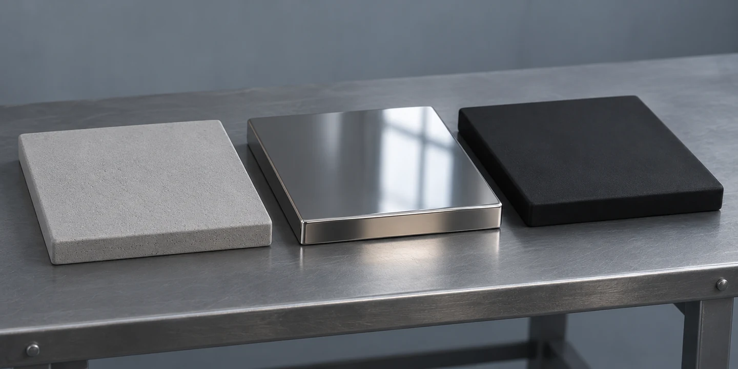
实际零件的光洁度和方向决定接收器是否可以识别预期位置。这些样本展示了三种值得单独测试的饰面。
| 目标或条件 | 光学风险 | 如何认定头部合格 |
|---|---|---|
| 浅色哑光漆或陶瓷 | 在一种设置下的强烈返回可能会在另一种设置上产生夹角,并且纹理会随着光点的移动而改变读数 | 检查近处和远处位置、代表性纹理和所选采集速率的响应 |
| 深色橡胶或涂层金属 | 弱图像可能会增加散射或导致测量缺失,尤其是在曝光时间有限的情况下 | 全速运行允许的最暗终点并记录可接受的值和无效值 |
| 抛光金属或光滑弧形塑料 | 当表面法线发生变化时,狭窄的回波可能会远离接收器或使其饱和 | Test the full angular envelope in the head's prescribed diffuse or direct-reflection geometry |
| 透明玻璃、薄膜或半透明聚合物 | 从不同界面返回,透射光或次表面散射可以移动或分割检测到的图像 | 将目标脸部移动已知量,改变背景并验证头部跟踪哪个界面 |
| 交替饰面或干湿部件 | 即使高度恒定,光学响应也会发生变化。曝光变化也可能影响过渡行为 | 通过跨饰面相同高度的生产序列,然后以已知的物理步骤重复 |
| 灰尘、薄雾、油污或附近的照明 | 窗户可能会失去透射,杂散反射或环境光可能会与所需的返回光竞争 | 将清洁和预期的操作条件与最终就位的防护罩、窗户和邻近设备进行比较 |
如果设备提供光学诊断,请查看光学诊断。即使报告值保持在范围内,弱峰、削峰、变化的背景或两个似是而非的峰也可以解释距离变化。塑料部件可以通过穿透拓宽接收到的峰值,这是某些头具有特定于材料的设置的原因之一。对于清洁测试,将两个饰面放置在同一平面上并将它们平移到横梁下。将报告的变化与独立的高度检查进行比较。材料边界处的明显步骤是在调整拒绝阈值之前调查返回或安装的证据。 Micro-Epsilon optoNCDT 1320 操作说明
当发射器、接收器和目标按照制造商指定的几何形状对齐时,专为直接反射设计的头部可以适应受控的镜状表面。不同的激光波长可以帮助处理某些目标,包括某些半透明或发光材料,具体取决于光学穿透力和背景光。一些蓝色激光头还使用专用的直接反射光学器件。使用确切的型号检查目标和所需的接口。对于透明厚度,需要明确设计的头或系统来分离相关界面并考虑材料和几何形状。 Micro-Epsilon 蓝色激光和直接反射示例
使光点和接收器视图适合该要素
光斑尺寸定义了对回报有贡献的区域。距离分辨率描述了头部在特定条件下可以辨别的深度变化的大小。头部可以区分距离的微小变化,而其光点比该站要测量的特征要宽得多。在一个步骤中,两个级别可以贡献一个探测器图像。输出可以在电平之间切换、落在电平之间或变得无效,具体取决于哪些返回到达接收器以及传感器如何解释它们。
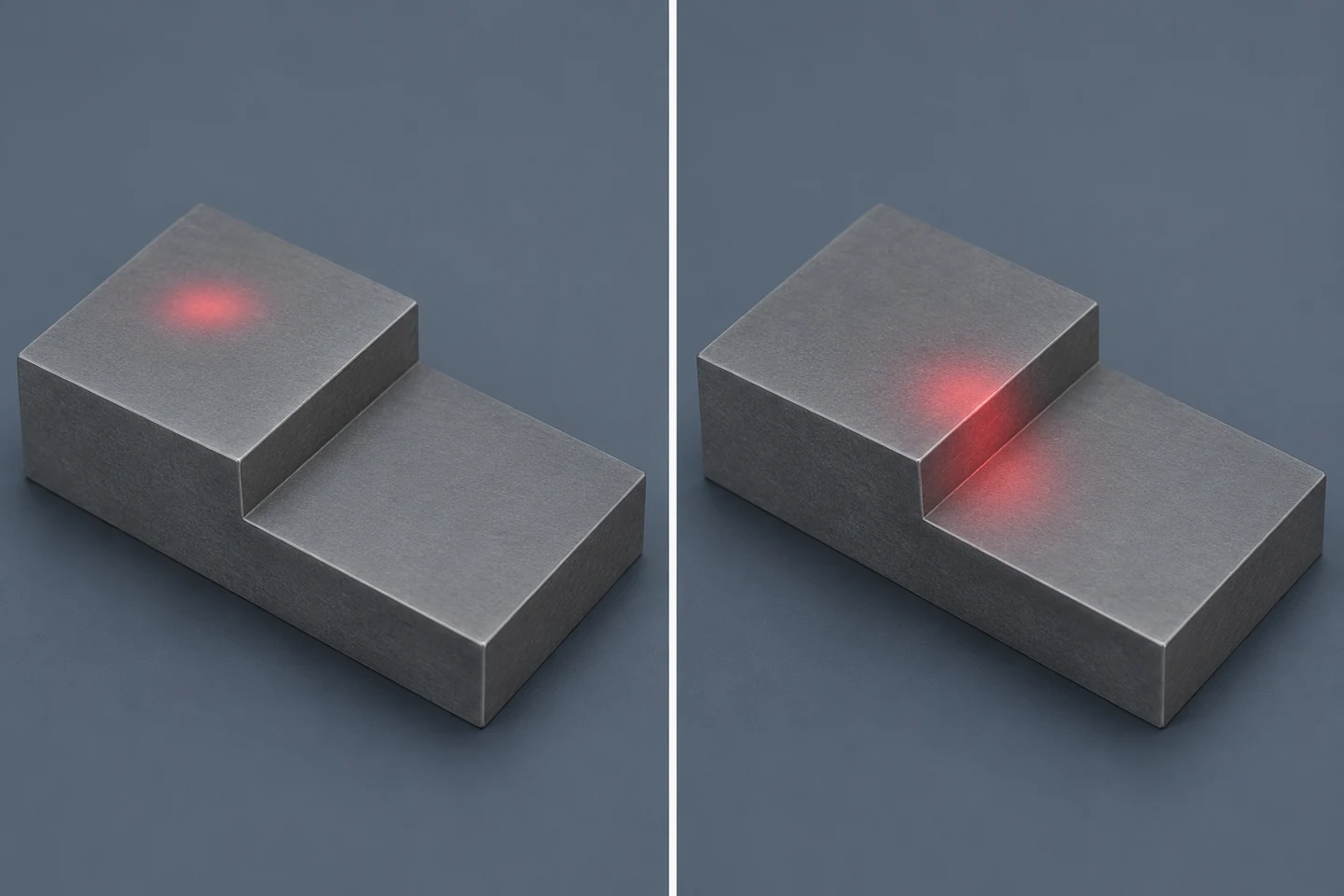
Use samples from the terrace interior for step height. When illumination spans the edge, the reported value depends on the competing returns and the head's processing.
Use the footprint dimension along the direction in which the feature crosses the beam. A quoted diameter typically uses a defined light intensity and leaves some light outside that boundary, so a nearby bright edge can still influence a nominally centered measurement. For an elliptical spot, this depends on head orientation. Tilt can also enlarge or move the projected footprint. Include placement variation across guides or fixtures and allow room for the real transition, such as a chamfer, radius or burr. Measure those allowances on production parts. Rotating a head may improve the footprint orientation, but also rotates the receiver's view. On a rough continuous surface a broader footprint can reduce sensitivity to individual texture peaks, while on a narrow land it can erase the useful measurement window.
At a recess, a clear path for the emitted beam establishes only half the geometry. The offset receiver also needs a view of the illuminated area. A wall can block that view at one end of the gap range or when the part drifts in the guide. Check the optical drawing in plan and side elevation with the worst expected part pose. Where changing the head orientation is allowed, try placing the receiver along the recess and verify that both paths stay clear. For a rotating cylindrical part, start near the intended radial line and test axial wander, eccentricity and surface angle over a revolution. Panasonic's product guidance shows examples for moving steps, rotating objects and recesses. The drawing of your selected head determines the installation orientation. 松下 HG-C 安装指南
计算该生产线可以捕获多少有用样本
对于恒定速度的输送机,将线速度除以有效采样率即可得到样本之间行进的距离。使用评估该功能的逻辑可用的速率。头部可以以几千赫兹的速度采集数据,而控制器每次扫描仅读取一次最新结果。如果传感器或数据模块以其定时或编码器位置缓冲每个样本,则较慢的控制器仍然可以使用较高的速率。确认数据流是否包含每次采集、抽取更新或重复值。区分输出节奏和响应延迟。
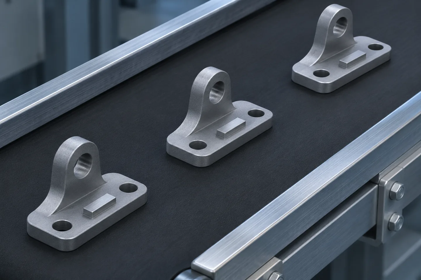
仅每个移动垫的内部可用于估计顶部高度。如果报告的值为台阶高度,控制器还需要在下基准面上进行单独测量。
考虑一个测量在加工零件上移动的台阶的工作站 600毫米/秒。上部土地是 1.60毫米 长途旅行。在允许的最差距离和方向下,假设沿行程的足迹为 0.40毫米。进一步预约 0.10毫米 在每个边缘处,以确保配准和边缘过渡的不确定性。对于此设计示例,至少保留预期的样本中心 0.20 + 0.10 = 0.30 毫米 从每个边缘。可用长度为 1.60 − 2 × 0.30 = 1.00 毫米。下层露台需要有自己的可用窗户,以同样的方式进行。
每秒传送 4,000 个样本时,间隔为 600 ÷ 4,000 = 0.15 毫米。由于间距均匀且无丢失,无论样本相位如何,1.00 mm 窗口中至少有 6 个标称样本中心。每秒传送 1,000 个样本时,间距为 0.60 毫米,仅提供一个保证的标称中心。即使静态重复性非常好,每个特征需要多次有效测量的配方也会对该速率下的相位敏感。
现在假设头部使用四样本因果移动平均值,在每次采集时更新。在每秒 4,000 个样本的情况下,每个平均值中第一个和最后一个样本的中心为 三个间隔或 0.45 毫米 分开。对于位于 1.00 mm 可用窗口内的每个贡献样本,最新样本的位置仅跨越 0.55毫米。在相同的理想时序假设下,只能保证三个完全支持的输出更新。相邻平均值也共享样本。三个平滑更新并不能提供与三个独立测量相同的统计证据。站点可以使用未经过滤的流,按位置收集有效样本,并在每个露台窗口内计算稳健的结果。基准数据可以显示需要进行多少过滤。
以此速率的四点移动平均线将其支撑中心向后移动 1.5 个样本周期,或者 0.375 毫秒。完整的系统可以增加曝光、传输、输入转换和处理时间。如果完成的测量在相关目标位置后 3 毫秒到达控制器,则零件已移动 1.8毫米 以 600 毫米/秒的速度。将这样的值与当前传送带位置相匹配可以将门完全移离垫板。测量预期信号路径的端到端延迟。如果时间很重要,请在采集时捕获编码器位置或同步时间戳。绑在皮带上的编码器仍然需要检查零件滑动或独立的零件触发器。
Check exposure time on the darkest approved target at maximum speed. The part moves during each exposure, so the return can include motion across the finish or edge even when the sample centers seem adequately spaced. If exposure is automatically adjusted, compare the relevant settings or diagnostics on bright and dark lots and across the transition between them. Allow for jitter, delays and invalids before deciding that a marginal sample count is acceptable. Set the acceptance gate and minimum valid sample count for each terrace. If either terrace lacks enough valid data, route that part through the inspection system's defined unresolved-measurement path.
处理输出端的无效测量
询问确切的模型如何报告光线太少、饱和度、范围错误或断开的链接。有些头提供故障状态或不同的输出值。其他可以配置为在多个周期内保持最后的有效距离。因此,未改变的合理距离可能是陈旧的。例如,optoNCDT 1320 手册记录了显式错误输出和保留最后值的模式。确认配置的行为如何出现在实际控制器输入上。 Micro-Epsilon optoNCDT 1320 操作说明
Log validity or error state alongside the distance, trigger position and timestamp where supported. Check whether a held value is marked as held, whether the hold counts acquisition cycles, and whether the PLC can distinguish freshness when communications stop. For an analog connection, verify scaling, input range, noise and the response to the manufacturer's specified error signal. For a digital connection, verify units, sample counters or timestamps, and behavior when frames are missing. Try a known target loss during commissioning and check what the final decision logic records.
安装头部并验证组装后的测量结果
Choose a short, stiff mounting arrangement tied to the machine datum. An independent support that moves relative to the part can look like real target displacement. Check bracket movement with actuators cycling, under changing cable loads and as equipment warms. A stationary target referenced to the machine frame can help separate sensor or fixture motion from part variation. Tighten to the head and bracket manufacturer's mounting instructions and provide repeatable locating features if the head must be removed for service.
Keep both optical paths accessible for cleaning and protection. A shield can stop stray light yet obstruct the receiver at the far position. A protective window can add reflections, contamination or a geometry change, so test the installed window and its exact orientation. Verify that nearby heads do not interfere when they run together. Carry the model's installation instructions and laser classification into the machine's integration review.
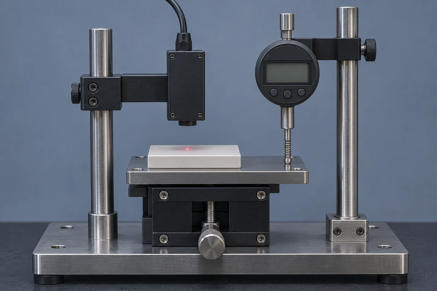
在工作台上,目标和指示器接触点在同一个刚性平台上移动。最小化间距并检查指示器和激光位置是否经历相同的位移。
首先使用合适的独立参考进行静态检查,例如由具有足够不确定性的指示器读取的校准阶段,或尺寸特征的阶跃工件。检查多个位置并从两个方向接近位置。如果可行,请使用与安装的测量相同的夹具和几何形状。对于载物台,请保持参考轨道和激光轨迹足够接近,以使载物台间距对差异影响很小。参考线和激光接触线之间的较大间隔可能会将微小的旋转转变为明显的行程差异。将参考方法和不确定度与结果一起记录。
Zeroing against a known part aligns one point. It can correct an offset at that position while leaving a slope error, a range-dependent deviation or a surface-related bias. After zeroing, verify near, nominal and far positions with independent references. Return to nominal at the end of the sequence to check drift or seating. Then repeat with representative parts, since the artifact's finish can give a cleaner optical signal than the surface encountered on the line.
| 调试试用 | 需要改变什么 | 记录和比较什么 |
|---|---|---|
| 固定参考移动 | 近、中、远位置,从两个方向接近 | 每个位置的参考值、平均读数、偏差和重复分布 |
| 制作完成及姿势 | 完成极限、刷牙方向、目标倾斜、横向移动和代表性批次 | 匹配参考、诊断信号和无效计数处的表观高度 |
| 动态特征运行 | 从慢速到全速、不同的触发阶段、现实的间距和滤波器设置 | 每个窗口的最小可用样本、测量步骤和控制器延迟 |
| 机器状态和环境 | 预热、振动、照明、相邻头、安装的窗户以及合理代表性的污染 | 参考漂移、噪声、无效率变化和中断 |
| 决策路径 | 已知的可接受和不可接受的特征、边界值、缺失目标和过时的读数 | 最终决定、零件标识、错误状态和不确定情况的处理 |
在运行这些试验之前,设置实际任务的接受限制。位移反馈回路需要有关延迟和可用运动带宽的证据。质量站需要定义的允许误差、最小有效样本计数、无效测量策略以及决策在其容差限度附近仍然可靠的证据。按功能和部件跟踪无效样本。较小的平均无效率可以隐藏用于做出决策的短特征上反复出现的失败。
如果结果仅在生产速度下恶化,请比较原始信号、处理的距离和控制器存储的值。原始返回在光学或几何学的边缘点附近破裂。干净的未过滤距离轨迹,后面是经过圆形处理的平台,指向过滤。干净的传感器流与错误部件位置处的值配对表明接收系统中的定时、数据关联或丢失。如果每当执行器启动时固定参考就会移动,请在重新调谐滤波器之前检查结构和参考夹具。
通过测量记录保留型号、固件、安装位置、设置文件、灯光模式、采样率、平均值、输出缩放和有效性行为。在机器文档中标记参考表面和选定的零件窗口。更换头部、更换固定装置、添加保护窗或新的饰面应促使重复检查这些变化可能影响的情况。
常见问题
一台激光位移传感器可以同时测量黑色和闪亮部件吗?
如果最暗的饰面以线速度提供足够的信号,并且最亮或最有光泽的饰面在允许的角度上保持可解释,则单个头可以处理这两种情况。测试完成的顺序以及每一项单独的测试。一些有助于黑暗表面的曝光设置会改变边界附近的响应。使用机器将使用的相同设置和光学器件以生产率测量偏差和无效值。
我可以使用重复精度为 1 µm 的传感器测量 0.2 mm 宽的特征吗?
仅当有效足迹、零件放置和接收器视图在特征上留下可用区域,并且生产线在该区域提供足够的有效样本时。 1 µm 数字描述了在规定条件下的重复距离测量。它没有提供有关最小特征宽度的直接证据。从安装间隙上的点尺寸开始,并考虑边缘、运动和对齐。
使用更长的范围是否会使传感器更容易安装?
较长的范围可以吸收更多的间隙变化,但头部可能具有不同的工作距离、更大的光斑或更大的绝对线性误差。在相同的相关距离上比较各个模型并完成。如果支架和零件运动控制良好,则具有足够余量的较短范围可能会提供更好的配合。如果设置变化迫使范围变大,请检查最小特征在两端是否仍然可测量。
为什么距离稳定但错误?
稳定值可以是来自透明接口的偏置返回、错误的参考偏移、缩放误差或丢失信号后保持的结果。将预期表面移动已知量,并一起检查原始诊断、有效性和最终控制器值。然后改变背景或附近的反射表面,同时固定预期目标。通过这些检查,正确的输出应该遵循预期的表面。
我可以平均两个打印头读数来消除纸张运动吗?
对于相对头的厚度,使用校准间距减去两个向内间隙的总和。两个头必须同时观察相应区域才能取消共同的垂直运动。在倾斜或移动的板材上,不等的横向位置或延迟会增加明显的厚度变化。将这对与已知厚度的预期运动、角度和速度进行比较。
我应该要求传感器供应商展示什么?
提供零件样品、两个光路的图纸、允许的距离和倾斜、最小特征宽度、线速度、公差和预期的控制器接口。请求演示距离误差、响应和极端情况下精确光学和输出设置的无效处理。询问可用的原始数据或诊断数据,并验证生产夹具上建议的设置。演示目标的固定结果只能回答部分选择问题。





发表评论