
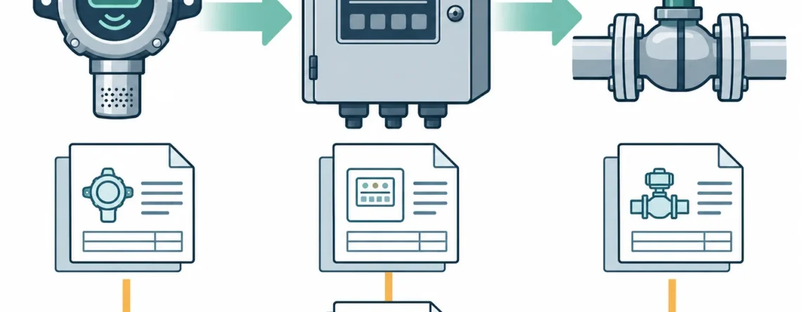
Review gas alarm and interlock documentation by following each initiating condition through the detector, signal path, controller logic, annunciation and final equipment response. The documents should distinguish gas alarms from detector faults, explain every inhibit and reset condition, and connect the intended behavior to evidence from the installed system. A detector calibration certificate establishes a narrower claim than a verified shutdown chain.
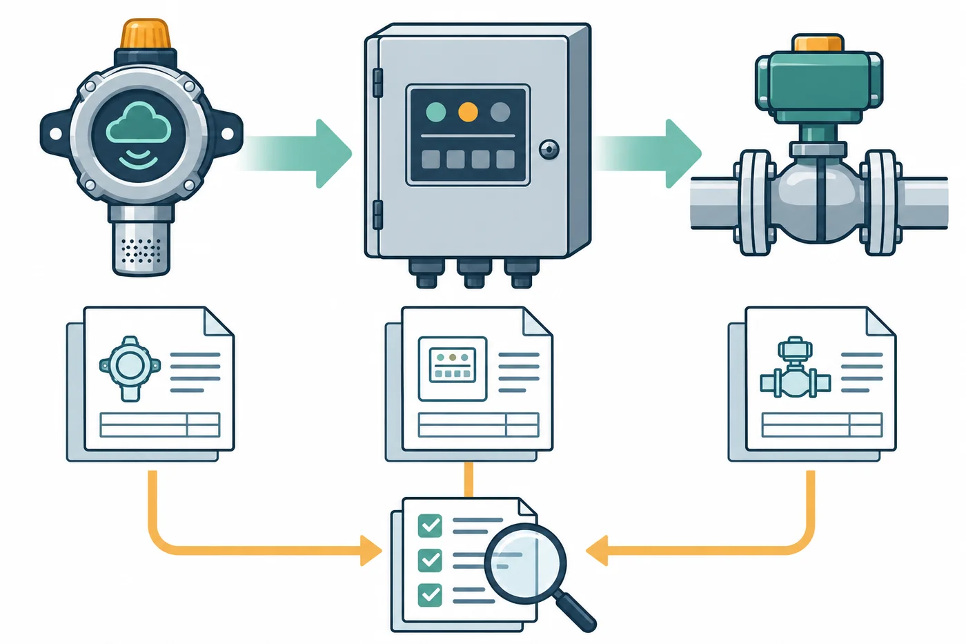
Concept illustration: separate components require evidence at their interfaces; the drawing is not an approved installation.
This is a framework for reviewing an existing design and its evidence. Actual settings, test methods, isolation arrangements and restoration authority belong to the approved site design and applicable equipment instructions. A room gas alarm, process trip and safety instrumented function may share equipment while having different requirements. Start by establishing which function the documents actually claim.
Start with the claimed protective function
Ask the design owner to describe the function in one complete sentence: which hazard is detected, where it is detected, which condition initiates a response, and which response is required. “Gas alarm system” is too broad. It could mean a local sounder, a message at an attended workstation, ventilation control, gas isolation or a combination with a defined sequence. Each outcome needs a clear boundary and an owner.
Identify the premises, process and jurisdiction before comparing documents. A commercial catering gas interlock is not automatically equivalent to an industrial combustible-gas shutdown system. A personnel exposure alarm is not automatically an equipment protection setting. Product certification also has a scope: an approved transmitter does not certify every connected controller, valve, communication network and application as a complete protective function.
Create a function register with a stable identifier for each claimed action. Link it to the hazard assessment, design narrative and relevant drawing revisions. Where several detector channels contribute to one action, list them explicitly. Where one channel performs several actions, keep those outcomes distinguishable. This makes it possible to discover a missing action without assuming that an alarm banner represents all downstream behavior.
The register should also identify whether the function is continuously required, required only during particular operating modes, or subject to approved restrictions. Maintenance, startup and shutdown can change the necessary protection. A document that describes only steady operation leaves a significant question unanswered: what does the system do while the process or the detector is transitioning between states?
Assemble a document set with consistent identities
Useful records normally include the hazard assessment, approved cause-and-effect schedule, instrument list, loop drawings, controller configuration, equipment manuals, commissioning results and change history. Their exact names vary. The important question is whether they describe the same installed system and the same approved revision. A large folder is not a substitute for agreement between these documents.
Read equipment tags across the set. The detector tag on a layout should match the tag in the controller input list, alarm list and test record. A service contractor's reference number may help locate a job, but it cannot replace the site's persistent identity. For remote sensors, separate the transmitter identity from the sensing head identity so that maintenance does not silently break the history.
Check gas name, units and range at every displayed and transmitted value. A combustible-gas channel may use a calibration-gas basis and configured correction that need to be understood before its value is compared with another device. A generic “LEL” description does not explain the exact instrument basis. The HSE guidance on flammable gas detectors specifically treats correction factors as model dependent; it should not be read as a universal conversion table.
Document discrepancies should remain visible until resolved by the responsible owner. Do not choose the newest-looking page merely because it has the latest print date. A configuration export may be current but unapproved, while an older approved drawing may no longer represent the installation. Record both facts. The review needs a controlled resolution, not an undocumented guess about which file should win.
| Evidence object | Question it should answer | Common unresolved mismatch |
|---|---|---|
| Hazard assessment | What harmful event requires the response? | Gas list differs from the installed channels |
| Cause-and-effect schedule | Which cause produces which action? | Narrative and matrix name different final elements |
| Loop and termination drawings | How is the signal carried? | Field tag differs from controller input |
| Configuration record | What logic and settings are installed? | Export has no approved revision relationship |
| Functional test record | What was actually observed? | Detector display checked but final action omitted |
| Restoration record | What operating state was re-established? | Inhibit removal is assumed rather than confirmed |
Read a cause-and-effect matrix as a set of claims
The matrix should distinguish individual initiating conditions and identify the effects they cause. Gas warning, higher alarm, detector fault, loss of power and communication failure are different conditions. A matrix may intentionally give them some common effects, but that relationship should be explicit. A single row labelled “detector activated” obscures the behavior that matters during a failure or maintenance event.
For each cause, look for the initiating tag, condition, configured threshold basis where relevant, time behavior, operating modes and any voting arrangement. For each effect, identify the output and required equipment state. “Ventilation on” can mean a command has been issued, a starter has changed state, or airflow has been demonstrated. These are different claims and require different evidence.
Read notes as carefully as matrix cells. A note can define a delay, inhibit an action during startup or require manual restoration after the initiating condition disappears. If a note changes several rows, establish how it is implemented and tested. It is easy for a spreadsheet revision to add a qualification that never reaches the controller logic or test procedure.
The review should separate intended behavior from test observations. The approved matrix states what should happen; a test record states what happened under identified conditions. Neither document replaces the other. A completed test without a traceable requirement can demonstrate repeatability while still proving the wrong response. A complete matrix without observed evidence leaves implementation unresolved.
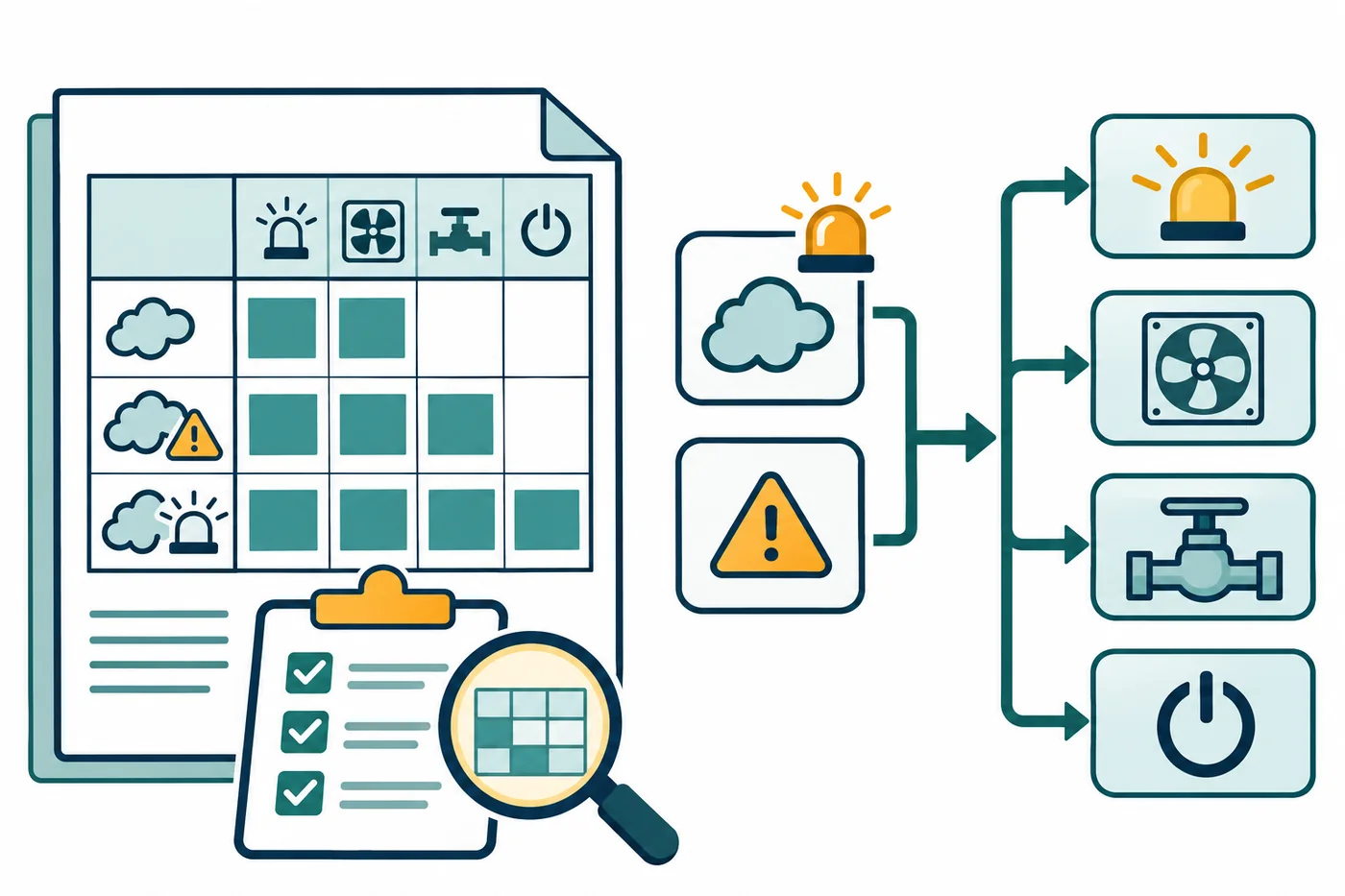
The matrix links a defined cause to a defined effect. Generic symbols do not specify settings or an approved response.
Distinguish contact labels from operating states
Relay documentation often uses terms such as normally open, normally closed, normally energized, latching and non-latching. These terms describe different attributes. A terminal label does not by itself tell the reviewer what the connected equipment does during a gas alarm, an internal fault or loss of power. Read the manufacturer's state definitions together with the installed wiring and configured logic.
这 Rosemount 925FGD installation manual, September 2024 illustrates why model detail matters. It describes configurable alarm relays and a separately defined fault relay. These descriptions cannot be generalized to another transmitter merely because both products have three relays. The useful review question is whether the actual configuration and wiring implement the approved state table.
Prepare a state table that distinguishes normal healthy operation, each alarm state, fault, power loss, startup and maintenance. Include both the device output and the resulting equipment state. Where a communication value is involved, identify the receiving system's treatment of bad quality, missing updates and restart. A retained number can remain visible even when the measurement is no longer current.
Avoid treating the phrase “fail-safe” as a complete explanation. Ask which failure is addressed, which state results, and which other failures remain outside that claim. De-energizing a relay may support a particular design objective while leaving contact welding, incorrect wiring, a mechanically stuck valve or unavailable utility power to be addressed elsewhere. The documentation should describe those boundaries clearly enough for the design owner to assess them.
Keep alarm acknowledgement, reset and restart separate
Acknowledgement can silence or recognize an indication without removing its cause. Reset can release a latched logic state after defined conditions are satisfied. Restart can restore equipment operation or gas supply. These actions may have different permissions, different prerequisites and different consequences. A screen button labelled “reset” is insufficient evidence of what happens throughout the connected system.
Review what occurs when the gas concentration falls below the alarm condition. Does the indication clear automatically? Does an interlock remain latched? Does equipment remain stopped until a separate authorized action? The correct answer depends on the approved design. The record should show that the behavior was understood and checked, rather than treating the disappearance of an alarm as permission to restore the process.
这 Flamefast GASGUARD manual GG_OM_0224 provides a useful application-specific example of a commissioning checklist that separates system operation from interface checks. Its gas proving and interlock functions belong to that product and application. The broader documentary lesson is to preserve evidence for each relevant interface and restoration condition instead of recording only a single overall tick.
Also examine behavior after power returns. Automatic controller restart, restoration of a network connection and recovery of a detector do not necessarily justify automatic process restart. The approved narrative should identify the required transition. If the documentation says only “returns to normal,” ask whether that means an electrical status, an alarm status or actual equipment operation.
Define the boundary of each test
A calibration or concentration comparison addresses a measurement claim under stated conditions. A detector functional check addresses response to an applied challenge and the functions actually observed. A loop check can address transmission and scaling. An interlock test can address logic and final equipment action. These labels are useful only when the record identifies exactly what was included.
An electronic input simulation at the controller may demonstrate logic while excluding the sensor, the local gas path and part of the field wiring. A gas challenge at the sensing head may demonstrate detector response while downstream actions are deliberately isolated under an approved test arrangement. Both activities can be valuable. Neither should be described as proof of the entire installed protective chain without the additional evidence.
For every test, identify the stimulus, injection point, observed outputs, excluded elements and acceptance criteria. Record the operating mode and any temporary inhibition that changes the expected response. A field report that says “alarm passed” but does not name the observed indication or equipment state is difficult to interpret later. Ask for clarification rather than expanding its scope by assumption.
这 Det-Tronics PIRECL safety manual 95-8630 revision 5.2 contains model-specific proof-test requirements and restoration provisions. Its use of a gas response test belongs to listed safety-certified models and the documented safety application. Do not substitute a portable monitor's generic bump-test label for that safety manual's defined test coverage, conditions or acceptance criteria.
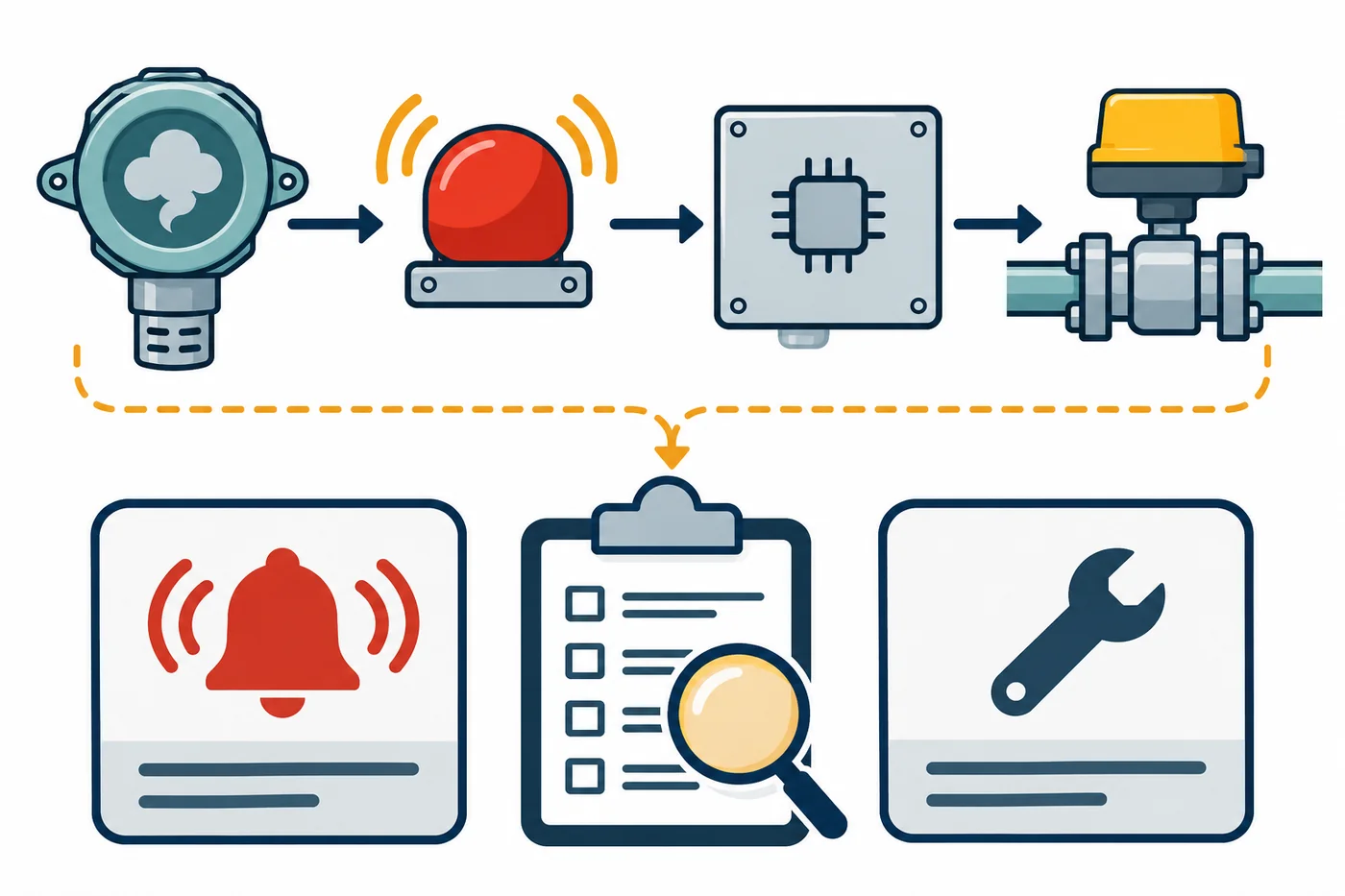
An alarm and a fault convey different information. The response to either must come from the approved design.
Review inhibits as temporary changes to protection
Maintenance and testing can require controlled temporary changes, but an inhibit is not merely an administrative note. It changes which response remains available. Review the authority, scope, duration, indication and compensating arrangements attached to the temporary state. The records should identify the affected channels and effects, rather than relying on a broad description such as “gas panel isolated.”
Different layers can contain different inhibits. A transmitter can suppress its outputs during maintenance, the controller can inhibit a channel, and another control system can prevent a final action. Removing one does not prove the others are removed. A restoration checklist should follow the actual layers used and state what evidence establishes their final condition.
Check whether the test report preserves unresolved restrictions. If a final element could not be exercised, record that limitation and the action needed to close it. A partial test should not acquire the appearance of complete acceptance when copied into a summary spreadsheet. Clear labels such as “detector response observed; valve action excluded” make a later decision much more reliable.
Ownership matters during shift changes and contractor handovers. The person performing a test may not own the process operating decision. Identify who receives an incomplete result, who tracks the restriction and who is authorized to accept restoration. This is a document control issue with a direct operational consequence: a technically accurate test can still be misused if its limitation never reaches the person relying on the system.
Look for evidence at interfaces and shared services
An interface can fail conceptually even when each individual device meets its own specification. The transmitter's output range can differ from the receiving channel's scaling. A controller output can be correctly wired to a terminal that performs a different function from the design narrative. A communication message can reach a workstation that is not attended during the relevant operating period.
Review shared power, communication paths and supporting utilities at the level required by the approved design. If several channels depend on the same component, their apparent independence may be limited. This review does not calculate system reliability from a document list. It identifies where the design claim needs supporting analysis and where the records should avoid implying independence that has not been established.
Final elements deserve their own identity and evidence. A commanded valve closure differs from confirmation of the required isolation performance. A commanded fan start differs from the ventilation outcome specified by the design. The test plan should state which outcome it verifies. Where a separate specialist test establishes another aspect, link that report explicitly rather than treating an electrical output as evidence for a mechanical property.
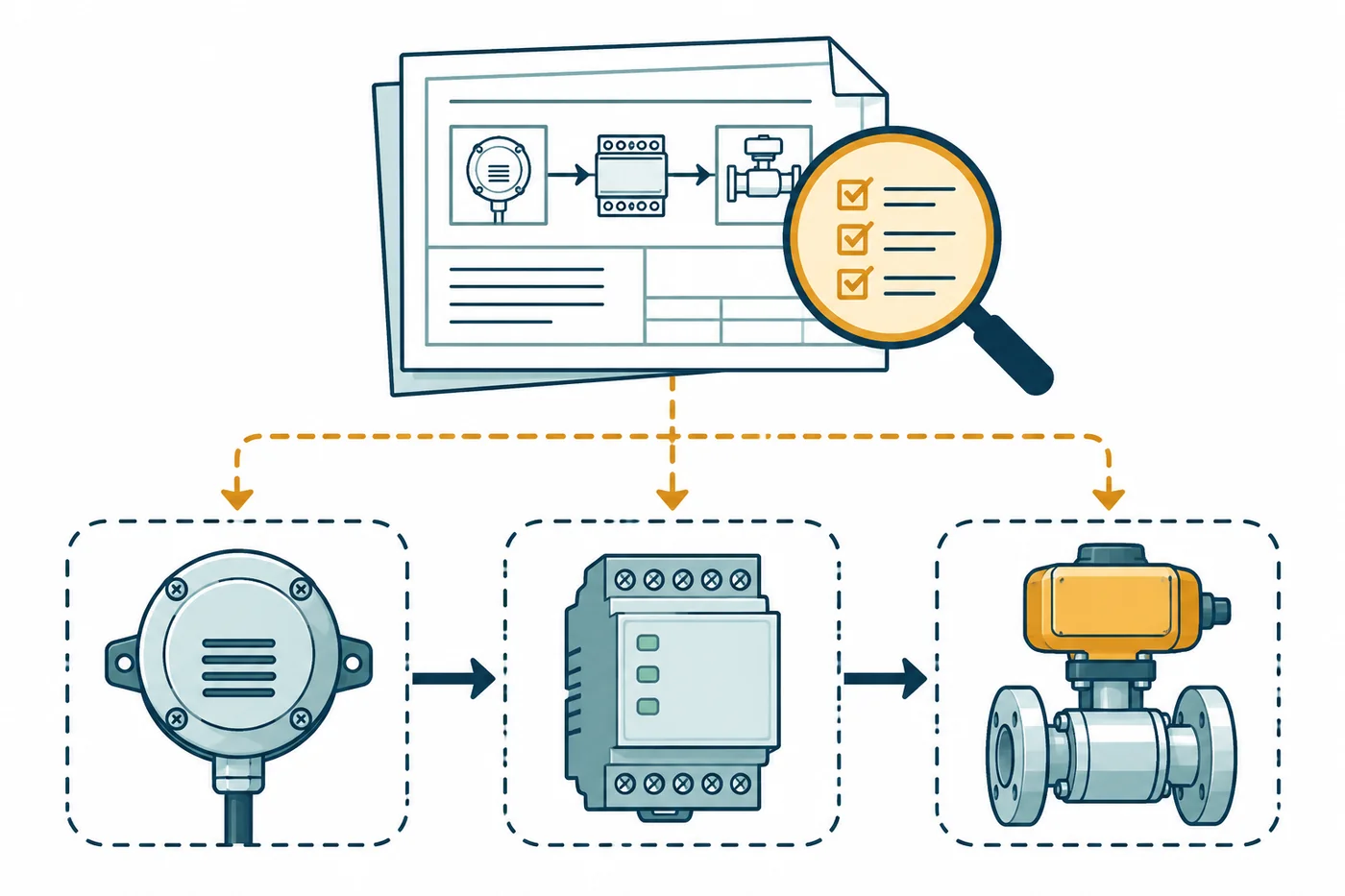
Each boundary requires a stated observation. A successful signal transfer does not automatically establish the final mechanical outcome.
A hypothetical review with two different gaps
Consider a hypothetical workshop where the approved narrative calls for a gas alarm to produce a local warning and an equipment interlock. The service folder contains a recent detector calibration result and a controller test sheet. The calibration identifies the detector serial number; the controller sheet identifies the input channel. Neither document records the connected equipment's response.
The reviewer should first reconcile the detector tag and channel mapping. If that relationship is supported by current loop documents, the two reports can be understood as complementary evidence for part of the chain. They still do not demonstrate the required equipment action. The missing evidence is specific: the final effect and its restoration behavior need to be addressed by the responsible test and design owners.
Now suppose a configuration export shows a non-latching output while the approved matrix calls for a retained interlock requiring authorized reset. That is a different gap. It is a contradiction between intended and recorded configuration, not merely an absent test sheet. The reviewer should preserve both records, assign the discrepancy and avoid rewriting the matrix simply to make it agree with the export.
No operating outcome is assumed in this example. The documents may eventually support a correction, a controlled design change or a revised evidence package. The valuable result of the review is a clear statement of what is established, what is inconsistent and who must resolve it. “System passed” would conceal both the unverified interface and the configuration contradiction.
Use a closure checklist that names evidence
Before closing the review, confirm that each claimed protective function has an approved requirement, traceable equipment identities and an identified evidence set. Check that test scope matches the claim, exclusions remain visible and every temporary change has a documented disposition. A signature should refer to that defined package and revision; it should not silently cover future changes.
- Match every initiating tag to the installed input and approved cause.
- Identify alarm, fault, startup, power-loss and communication-loss behavior separately.
- Reconcile gas, units, range, scaling and configuration basis across interfaces.
- Distinguish command, indication, equipment action and verified process outcome.
- Name the stimulus and observation boundary for each test result.
- Resolve discrepancies through the designated owner and controlled revision process.
- Record the final state of every inhibit and unresolved restriction.
- Preserve the evidence supporting reset and restoration behavior.
Keep the closed package accessible to maintenance and operations. A good review is useful beyond the acceptance meeting: it gives the next technician a trustworthy map of the system's intended response and the limits of earlier evidence. When a sensor, controller, final element or operating mode changes, the map makes the affected claims easier to identify.

Restoration is a defined transition with its own authority and evidence.
Classify discrepancies by the decision they affect
A useful discrepancy list says which claim cannot yet be supported. For an identity mismatch, the question is whether the tested object is the installed object. For a setting mismatch, the question is whether the installed response matches the approved basis. For missing final-element evidence, the question is whether the specified effect occurred. These are distinct routes to closure, even when they appear in the same commissioning folder.
Consider a test sheet that names the correct channel but an outdated detector serial number. The reviewer should not immediately reject every observation on the sheet. Establish whether the serial is a transcription error, whether the detector was changed after testing, or whether the report belongs to another instrument. The supporting evidence determines which observations remain applicable and whether any must be repeated under the approved plan.
A threshold discrepancy needs a different investigation. First check units, range and gas basis so an apparent numerical difference is not misinterpreted. Then compare the approved requirement and configuration history. A setting that differs from an old drawing can reflect an authorized change, an unapproved change or an obsolete drawing. Record the actual relationship rather than assuming that a difference is either harmless or necessarily a live defect.
An incomplete observation is different again. A report may document that the controller issued a command but omit feedback from the final equipment. That does not establish the equipment failed. It means the record does not yet support the broader claimed outcome. The closure action should name the required observation or linked report, keeping the result within the authorized test scope.
Use plain dispositions such as resolved by identified evidence, corrected and reverified, approved design change, or still unresolved. Each disposition should identify the affected function and revision. A closed maintenance work order is insufficient if it contains no evidence addressing the original question. This approach makes technical review more efficient because follow-up work is directed at the missing claim.
Preserve the response narrative through later changes
Once the package is accepted, changes to equipment, software or operating modes should trigger review of the affected functions. A replacement controller can retain the same tag while changing default output behavior. A new supervisory display can alter how bad-quality information appears. A revised process sequence can make a previously adequate restoration condition incomplete. Change review should follow functional relationships rather than only the parts physically replaced.
Keep a concise baseline describing the approved response and its evidence references. The baseline is useful when troubleshooting because it separates expected behavior from a technician's recollection of what the system usually does. It should point to controlled documents and test records rather than attempt to duplicate every setting in another uncontrolled spreadsheet.
After a change, establish which earlier results remain relevant and which claims require new evidence. An unaffected detector calibration may remain valid for its documented measurement scope, while changed controller logic requires a separate review. Conversely, a sensor change can affect the front of the chain even when downstream wiring is unchanged. The decision should state the reasoning, not simply reset every date or retain every old pass by habit.
Handover is complete when operations and maintenance can identify the current approved behavior, locate its supporting evidence and recognize outstanding restrictions. That practical accessibility matters: a technically thorough package hidden in an obsolete project folder can leave day-to-day decisions dependent on memory. The review should therefore include document location and ownership as well as technical agreement.
常见问题
Does a current calibration certificate prove the interlock works?
It proves only the measurement or service claim actually documented. Read the identified equipment, method, comparison points and results. Unless the report includes the relevant logic, outputs and final equipment observations, it cannot establish the complete interlock response. Link complementary evidence rather than broadening the calibration certificate's meaning.
Should every detector fault close the gas valve?
That is an application and design decision. A fault indicates a problem with available detection or related equipment; it is not a gas concentration measurement. The approved assessment and response design should specify the action for each relevant fault. Do not copy a shutdown response from another installation or assume every manufacturer's fault output behaves identically.
Can a simulated input replace a gas challenge?
They address different boundaries. Simulation can be useful for downstream logic and indication checks while excluding the physical sensing process. A gas challenge addresses the detector response under its defined method. The approved verification plan determines which evidence is required and how the parts combine. Record exclusions explicitly.
What if the as-built drawing and configuration disagree?
Record the discrepancy with the exact revisions and affected function. Establish the actual installation through the authorized review process and obtain the design owner's resolution. Updating a drawing or changing a setting can each be consequential; neither should be selected merely because it is easier to make the paperwork agree.
Is a safety-certified detector enough to claim a safety integrity level?
The detector's certification has defined models, conditions and assumptions. A complete function includes other elements and an application-specific design. The PIRECL safety manual is one example of a product document that defines particular obligations. A component label alone does not establish the complete installed function's achieved integrity.
Where does bump testing fit into this review?
Read the procedure rather than relying on the name. The existing Sensor1stop bump-test overview explains the general functional-check concept. In a fixed protective function, the manufacturer's safety manual and site verification plan may define a different or more extensive gas response test. Its documented scope is what matters.
Sources and equipment documents
- HSE:可燃气体探测器的选择和使用, guidance on detector selection, limitations and maintenance; its dated references do not establish current adopted standards.
- Emerson: Rosemount 925FGD installation manual, September 2024, model-specific output and relay descriptions.
- Flamefast: GASGUARD gas proving and interlock manual GG_OM_0224, application-specific commissioning and interface documentation.
- Det-Tronics: PIRECL safety manual 95-8630 revision 5.2, model-specific proof-test and restoration requirements.




发表评论