
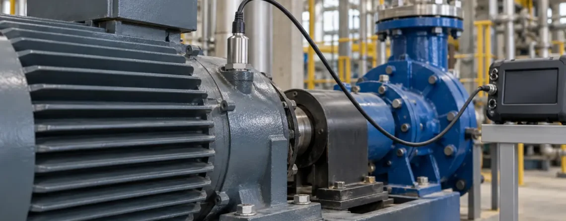
选择加速度计 您需要测量的运动、加速度范围和频带以及传感器的安装和读取方式. A three-axis MEMS device that measures gravity and slow tilt may be suitable for orientation monitoring. A piezoelectric vibration sensor may be a better fit for a particular machine's dynamic frequency range. The actual datasheet and installed measurement chain determine suitability; neither technology label guarantees the performance of a complete system.
Start by describing the decision: detect a change in a motor bearing, measure a shock, monitor slow structural motion, or estimate a stationary object's tilt. Then define the expected amplitude, relevant frequencies, environment, sensor location and output. This approach makes the range, noise, mounting and sampling requirements measurable instead of selecting a sensor solely because it has a familiar name.
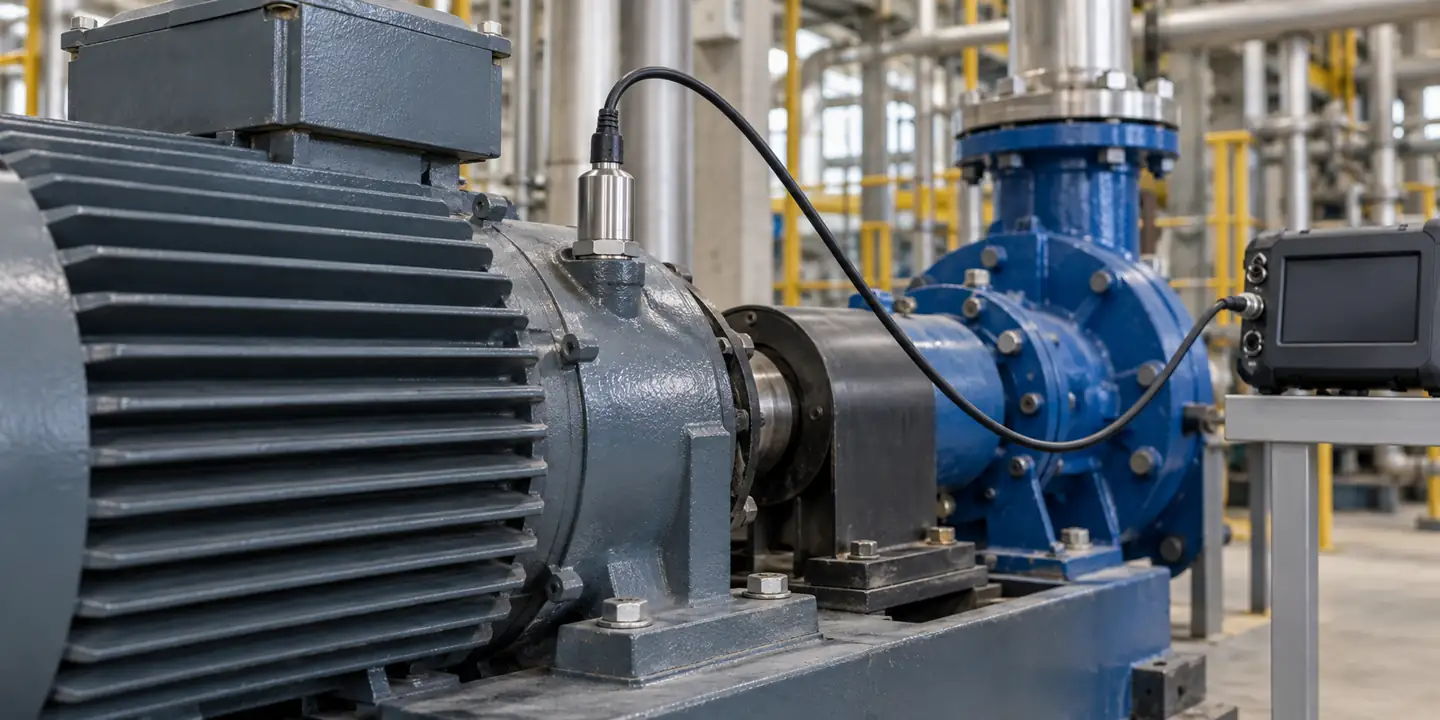
加速度计测量什么
加速度计测量其传感元件相对于自由落体所经历的加速度,通常称为 适当的加速. At rest on a table, a DC-responsive accelerometer senses the support force associated with gravity. In free fall, an ideal accelerometer reads approximately zero even though the object accelerates relative to Earth. The sign and axis depend on the device's orientation and its coordinate convention.
For a stationary or slowly moving object, the gravity components across axes can be used to estimate tilt. During translation, vibration or rapid rotation, the measured signal also contains motion-related acceleration. A single instantaneous reading cannot always distinguish tilt from linear acceleration. Dynamic orientation systems commonly combine accelerometer data with other measurements and a suitable estimation algorithm; the appropriate approach depends on the accuracy and operating conditions.
An accelerometer does not directly measure displacement or velocity. These can be estimated by integrating an acceleration signal under suitable conditions, but bias, noise, unknown initial conditions and filtering can introduce large errors. For a specific machinery diagnosis, verify whether acceleration, velocity, displacement or another quantity is required and how it will be derived.
| 测量任务 | Useful measurement | Primary selection questions |
|---|---|---|
| Stationary tilt | Gravity components and stable zero-g behavior. | Does the device respond to DC? What are bias and temperature effects? |
| Machine vibration | Dynamic acceleration over a defined frequency range. | Does the installed sensor and mount cover the frequencies and amplitudes? |
| Impact or shock | Peak and time history during a fast event. | Can the complete chain avoid clipping and sample the transient adequately? |
| Motion detection | Acceleration changes used to identify activity. | Are axis, range, power and decision latency suitable? |
| 结构监测 | Often small signals over low frequencies and long periods. | What noise, drift, synchronization and environmental controls are needed? |
How the sensing element produces a signal
Many accelerometers contain a proof mass supported by a mechanical structure. Acceleration changes the force on that mass, and a sensing mechanism converts the resulting deformation or displacement to an electrical signal. The sensor's mechanical response, electronics, package and filter all influence the result.
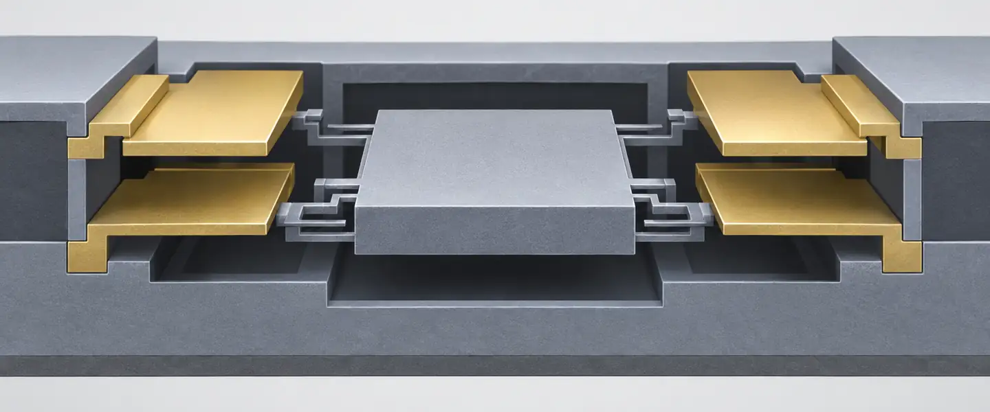
在电容式 MEMS 器件中,运动会改变传感器结构之间的电容。电子设备将这种变化转换为模拟或数字输出。许多设计可以测量静态加速度,但带宽、噪声、范围和输出取决于特定设备。 MEMS描述制造规模和机械结构;它不是单一的性能等级。
压电加速度计利用传感元件受压时产生的电荷。广泛用于动态振动和冲击。其可用的低频响应取决于传感器和信号调节。传统的交流耦合压电系统不提供静态倾斜的持续直流重力读数。检查完整的传感器和调节规格,而不是将短暂的瞬态响应视为稳定的倾斜输出。
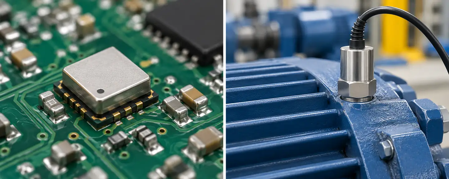
这 Analog Devices MEMS 选择指南 解释了为什么带宽、范围、噪声和偏置在不同应用中的重要性不同。 PCB Piezotronics' introduction describes piezoelectric vibration sensors and their conditioning. Use those principles to interpret an exact model's specifications rather than copying one example into a general requirement.
Range, sensitivity and clipping
The acceleration range is the input interval over which the device is specified to measure. A sensor can saturate or clip when an event exceeds its range, losing the real peak and distorting the recorded waveform. A mechanical shock survivability rating is not the same as a measurement range: a sensor might survive an event it cannot accurately record. Check both the sensing element and the acquisition electronics.
选择一个范围,其中包括预期的正常振动和具有适当裕度的可信瞬态。很大的范围可能会降低小信号的有用分辨率,具体取决于设备和输出配置。相反,在稳定运行期间表现良好的窄范围可能会在启动或冲击期间受到限制。如果系统提供可选范围,请验证灵敏度、噪声、输出格式和校准如何随设置而变化。
灵敏度描述了在定义条件下加速度变化导致的输出变化,例如 mV/g 或数字计数/g。它本身并不是可检测到的最小加速度。对于具有 100 mV/g 灵敏度的示例性传感器,在假设的线性条件下,2 g 动态信号对应于 200 mV。仍必须检查实际输出限制、偏置、频率响应和信号调节器。
一个标准重力 g 通常约为 9.80665 m/s²。指定振动数据是峰值、峰峰值还是 RMS 量。它们描述了不同的属性,在不了解波形的情况下不应互换。峰值和 RMS 之间的单一转换因子仅适用于特定波形,例如理想正弦曲线;这不是随机机械振动或冲击的一般规则。
噪声密度、带宽和最小有用信号
Noise limits the ability to distinguish a small signal from random output variation. Manufacturers may quote noise density in µg/√Hz and a total RMS noise under a defined bandwidth and filter. For approximately flat noise density and an idealized equivalent noise bandwidth, total RMS noise scales approximately with the square root of that bandwidth. Actual filter shape and other noise sources matter.
例如,假设平坦密度为 50 µg/√Hz,等效噪声带宽为 100 Hz,则该组件单独得出的 RMS 约为 500 µg:50 乘以 √100。这是说明性计算,而不是传感器规格或峰值检测保证。不同的滤波器、频率相关噪声或电子噪声会改变结果。 Analog Devices' definitions 描述其设备环境中的噪声密度和带宽。
减少带宽可以减少集成噪声,但它也会消除滤波器截止以上的有用运动。在缩小频带之前定义决策所需的频率内容。对于倾斜,偏置稳定性和与温度相关的偏移可能比高频带宽更重要。对于分析频带内的振动、噪声,安装和信号链可能占主导地位。 ADC 或数字输出的分辨率本身并不能确定测量精度或本底噪声。
频率响应属于已安装的系统
An accelerometer's frequency response states how its output changes with input frequency, often with a tolerance around a reference sensitivity. A datasheet's resonance frequency is not automatically the upper frequency limit for accurate measurement. Near resonance, response can be amplified and phase can change. Use the specified usable frequency range and tolerance for the exact model and mounting arrangement.
The sensor is mechanically connected to the structure through a mount. Studs, adhesive, magnets, brackets and handheld probes can change stiffness, mass and resonance. A soft or loose connection can attenuate or distort high-frequency motion. A heavy sensor can also alter the behavior of a light test structure. Compare the sensor and mounting assembly with the object being measured rather than treating mounting as a purely mechanical convenience.
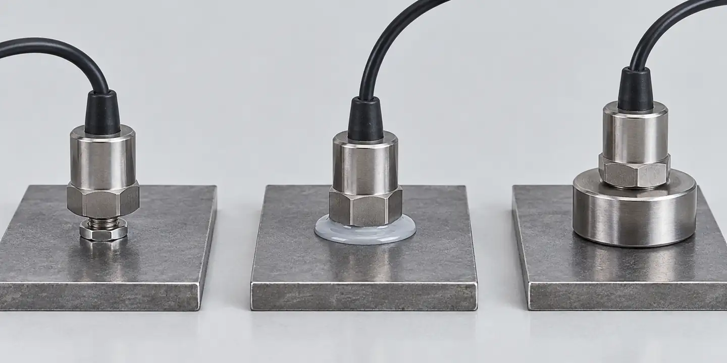
PCB Piezotronics' mounting guidance describes how mounting affects the usable response. A properly prepared stud mount can provide a stiff connection, but the right method also depends on access, surface, sensor design, safety and whether the installation is temporary. Follow the specific manufacturer's surface preparation, mounting hardware and torque instructions. Do not apply a generic torque or frequency limit to an unidentified sensor.
Sampling and aliasing
信号采样速度太慢可能会使高于奈奎斯特频率的频率分量出现在较低的、不正确的频率处。奈奎斯特极限是采样率的一半,但选择恰好两倍于感兴趣的最高频率的速率不会为真正的抗混叠滤波器留下实际的过渡带。一起选择速率、模拟或数字滤波和分析带宽。验证传感器或采集设备内部已有哪些过滤以及需要提供哪些过滤。
输出数据速率和传感器带宽相关但不同的规格。数字加速度计可以高速报告样本,而内部滤波器限制可用信号频带。相反,进入未充分过滤的采集路径的高频噪声或振动可能会混叠到感兴趣的频带中。这 Analog Devices 噪声性能说明 说明特定模型的过滤和带宽;它的数字不是通用设置。
为什么分析窗口很重要
Sample rate does not determine how well nearby frequencies can be distinguished. The length of the recorded time window and the analysis method also matter. For a simple Fourier transform, frequency-bin spacing is the sample rate divided by the number of samples, equivalently the inverse of the recording duration. A two-second record has nominal bins spaced 0.5 Hz apart; that statement alone does not guarantee two closely spaced components can be resolved, because windowing, noise and signal behavior also matter.
Short records can miss an intermittent event; long records can mix different machine states. Record the operating speed and load, and use analysis settings suited to the question. If a machine accelerates during a measurement, a frequency peak may shift during the record. A baseline gathered at steady speed should not automatically be compared with a transient without noting that difference.
处理链还可以改变报告的幅度。高通滤波器可能会抑制缓慢的趋势,而平均可能会隐藏短暂的影响。在可行时存储原始或最少处理的数据,以及采样率、滤波器、窗口和单位。该上下文可以让另一位工程师重现计算并确定稍后的更改是物理更改还是由配置更新引起的。
轴线、位置和安装方向
A single-axis sensor measures along its sensitive direction. A three-axis device supplies multiple components, but its axes still need to be aligned and documented. Mark the sensor's coordinate system relative to the machine or structure. A change in orientation can change a trend even when the underlying motion is unchanged. Cross-axis sensitivity and alignment error also matter when comparing small components.
Place a machine vibration sensor where motion relevant to the diagnosis transfers reliably into the sensor, often near the bearing or component of interest. A thin guard, loose cover or flexible bracket may have its own vibration response. The best location depends on the machine, fault mechanism and monitoring method; a sensor on a convenient panel is not necessarily representative of the bearing.
For a lightweight component, evaluate mass loading from the sensor, cable and mount. Route cables so they do not pull on the sensor, rub on moving parts or introduce motion. Check connector sealing and strain relief for the environment. Repeat measurements with the same position, axis and mounting method when trend comparability is important.
Electrical output and acquisition compatibility
MEMS accelerometers can provide analog voltage, digital serial data or a module-level industrial output. Confirm supply voltage, output format, scaling, sample rate and timing with the receiver. Digital values must be converted using the sensitivity and selected range for the exact configuration. A firmware change that changes filtering or data rate should be recorded with the measurement history.
Piezoelectric systems may use a charge output requiring a suitable charge amplifier, or an integrated-electronics design such as IEPE requiring compatible constant-current excitation and signal conditioning. Their wiring and supply requirements are different. A standard voltage input cannot be assumed to power an IEPE sensor correctly, and a charge-output sensor cannot be treated as an ordinary powered voltage transmitter. Consult the sensor and acquisition manuals for the complete combination.
这 NI vibration guide explains the relationship between sensor type, excitation, coupling and data acquisition. Check temperature limits for both the sensing element and its electronics, and note whether the stated cable length or connector arrangement affects the installation.
Consider power, temperature and the entire enclosure
The sensor's storage temperature, operating temperature and range over which accuracy is specified may be different. A device that survives a hot machine enclosure does not necessarily meet its room-temperature accuracy there. Check temperature effects on sensitivity and zero, as well as connector, cable and mounting limits. Repeated thermal cycles may also change a mount or cable routing even when the electronics continue to operate.
Humidity, washdown, oil and electromagnetic interference can affect the installed system. An enclosure rating should be interpreted under its defined test conditions; it does not automatically establish compatibility with a particular cleaning chemical or continuous immersion. For an outdoor or battery-powered installation, account for the acquisition device, communications and enclosure as well as the sensor itself.
When comparing low-power devices, use the current consumption for the actual output rate, filter setting and operating mode. A wake-on-motion feature may reduce average power but can miss or alter the record of events depending on its threshold and wake latency. Decide whether the system must retain the entire waveform or only flag an event, and test that behavior in the intended configuration.
Verify before relying on the trend

Record the sensor model, serial number, sensitive axis, mounting position, orientation, hardware, range, sample rate, filter settings and date of installation. Confirm that the instrument reports the expected units and that the acquisition channel uses the correct sensitivity. A value can appear plausible with a factor-of-ten scaling error, so verify the configured conversion against the sensor's calibration information.
For a DC-responsive accelerometer used for tilt, a controlled orientation check against gravity can reveal an axis or gross scaling mistake. It does not by itself establish dynamic frequency response, low-noise performance or full calibration. For vibration measurements, use a suitable reference or calibrator within its specified conditions. Record the input, frequency, sensor configuration and observed output; follow the applicable manufacturer or laboratory procedure.
| Symptom | Possible contributors | Useful first check |
|---|---|---|
| Flat-topped peaks | Sensor, amplifier or ADC clipping. | Review raw waveform, range and output headroom. |
| Unexpected high-frequency change | Mount looseness, cable motion, sensor response or a real structural change. | Inspect mounting and compare under the same machine state. |
| Apparent low-frequency drift | Bias, temperature, integration or motion of the support. | Review temperature and raw acceleration before integration. |
| Frequency appears in the wrong band | Aliasing or incorrect sample-rate configuration. | Check filters, data rate and acquisition settings. |
| Different results after replacement | Changed axis, mount, sensitivity or processing. | Compare installation records and configuration. |
Calibration supports traceability at stated conditions. It cannot guarantee that an installation has the correct mounting, bandwidth or location. A meaningful acceptance check follows the signal from the mechanical interface through sensing, conditioning, sampling, processing and display.
Selection worksheet
Write down the motion and the decision first. Then specify the frequency band and amplitude range, whether DC response is required, the number of axes, relevant noise and bias limits, mounting surface, environmental conditions, cable requirements and available acquisition interface. Include the highest credible transient and the smallest change that matters.
Ask vendors to identify the exact part number, frequency-response tolerance, measurement range, shock survivability, noise and temperature conditions. Request mounting and electrical requirements for the proposed configuration. If a filter, mounting base or external conditioner is needed, include it in the evaluation; a sensor-only specification cannot describe the complete installed response.
尽可能在有代表性的条件下进行试点。将安装的输出与合适的参考进行比较,并检查是否有削波、安装松动、混叠和不一致的操作状态。对于趋势应用程序,保留原始数据并记录处理设置,以便将来的读数可以在相同的基础上进行比较。
三个示例选择路径
固定外壳缓慢倾斜。 从直流响应传感器和定义的方向范围开始。询问零重力偏移、灵敏度误差、轴对准和温度如何影响推断角度。验证已知方向和预期温度条件下的读数。如果偏置稳定性不足以进行角度决策,那么具有出色高频响应的传感器可能没有多大价值。
Routine vibration trend on a motor. Identify the bearing or measurement point, expected machine speed, frequency band and normal operating condition. Select a sensor and mounting arrangement with adequate installed response and dynamic range; confirm the acquisition system supplies the correct excitation where required. Establish a baseline at a repeatable load and speed. A numerical change does not identify a particular bearing fault without the appropriate diagnostic context.
Short impact on a product. Estimate the credible peak and event duration, then check both measurement range and survivability. The sensor, conditioner and ADC all need enough headroom. Select sampling and filtering to preserve the event features of interest and use a mounting arrangement that follows the object without materially changing the event. Examine the raw waveform for clipping before reporting its peak.
These examples are design starting points, not universal part recommendations. A system may need multiple sensors or additional measurements to capture different locations, axes or operating modes. Selecting from a catalog should follow the field question and its uncertainty requirement.
Questions to ask before accepting a quotation
Which frequency-response tolerance applies to the proposed mounted configuration? Is the quoted range the linear measurement range or the survivable shock limit? Is noise stated as density or total RMS, and what bandwidth and filter were used? What are the sensitivity and zero changes over temperature? For a digital device, which output data rate and internal filter are selected? For an IEPE system, what excitation and input coupling are required?
Also ask how the sensor is calibrated, what reference frequency is used, and whether a calibration certificate applies to the complete assembly or only the sensor. These questions make apparently similar catalog entries comparable and reveal where a separate mounting or acquisition cost may be required.
Keep measurements comparable over time
For a monitoring program, give each measurement location a stable identifier and retain photographs or drawings of the sensor position and orientation. Record the machine's speed, load and operating mode at the time of the reading. A change in sensor position or processing can create an apparent trend even if the machine itself has not changed.
When a sensor is replaced, compare the new device with the previous measurement arrangement under a representative condition where feasible. Document sensitivity, calibration, cable, mount and filter settings. If exact comparison is not possible, annotate the change rather than silently joining two data series. A useful trend is one whose measurement conditions are known well enough to explain what changed.
常见问题
Can an accelerometer measure tilt?
A DC-responsive accelerometer can estimate stationary tilt from gravity components. During motion, linear acceleration and vibration can influence that estimate; dynamic orientation may require additional sensors and processing.
Is MEMS always less capable than piezoelectric?
No. MEMS and piezoelectric devices span different ranges of performance. Compare the particular sensor's bandwidth, noise, range, temperature behavior and interface against the task.
Does a high sample rate guarantee accurate high-frequency data?
No. Sensor response, mounting resonance, anti-alias filtering and acquisition bandwidth also limit the useful measurement band. A high output rate cannot recover motion the mounted sensor cannot measure accurately.
What is the difference between sensitivity and resolution?
Sensitivity relates a change in input acceleration to a change in output. Resolution concerns the smallest distinguishable change under stated conditions and depends on noise, bandwidth and signal processing.
Can I integrate acceleration to get displacement?
It is possible under suitable conditions, but offsets, noise, filtering and unknown initial conditions can produce substantial drift. Validate the resulting displacement for the intended frequency band and decision.
Is a magnetic mount equivalent to a stud mount?
Not necessarily. The added mass and stiffness of the mount affect mechanical response, particularly at higher frequencies. Test and use the manufacturer's guidance for the actual mounting assembly.






发表评论