

A dew point sensor is useful when the decision depends on whether water will condense at a particular process condition, rather than simply on the room's relative humidity. Choose the instrument only after defining the gas, the measurement pressure, the dew or frost range, and the point in the system the reading must represent. In compressed air, a reading taken after pressure reduction is not interchangeable with the pressure dew point inside the line. The sampling arrangement can therefore matter as much as the sensing element.
This guide focuses on water-vapor dew point in air and industrial gases, with compressed air as the main example. It also explains where an HVAC or building application calls for a different measurement location. The three common instrument approaches—chilled mirror, capacitive metal oxide and capacitive polymer—answer overlapping but not identical needs. Their suitability must be checked against a particular instrument's datasheet and the gas being measured.

Start with the measurement job
Before comparing sensors, write one sentence describing what will change when the reading changes. “Monitor moisture” is too vague. “Detect loss of dryer performance at the outlet while the distribution line is at operating pressure” identifies a location and a pressure basis. “Prevent condensation on a cooled duct surface” identifies a surface temperature and a different decision. These are not the same installation.
| Decision to support | Measurement to define | Common placement question | Main risk if poorly specified |
|---|---|---|---|
| Check a compressed-air dryer's output | Water-vapor dew or frost point at the intended reporting pressure | Immediately after the dryer and any specified after-filter? | A wet distribution branch may be missed, or an upstream point may be mistaken for outlet quality. |
| Check air delivered to a critical machine | Dew or frost point at the point of use, with process pressure recorded | Near the machine, after long pipework or a receiver? | A good dryer reading may conceal downstream moisture ingress. |
| Control a dry room or process enclosure | Moisture level over the relevant low range, with pressure and gas context | Representative return-air or process point? | A room RH instrument may not resolve the very dry conditions of interest. |
| Avoid condensation on an HVAC surface | Air dew point together with the actual surface temperature | Near the cold surface or relevant air stream? | A remote room reading may not describe the local boundary condition. |
| Verify a reference or calibrate another instrument | Traceable dew/frost-point measurement under controlled conditions | Laboratory or controlled sampling path? | A convenient field transmitter is assumed to be a reference standard. |
For the HVAC case, see our separate discussion of condensation around HVAC sensors. This article concentrates on specifying the dew-point measurement itself.
What a dew point reading actually means
Water vapor has a partial pressure in a gas mixture. At a fixed total pressure, the dew point is the temperature at which that water vapor would be saturated with respect to liquid water. Below freezing, instruments and standards may instead report a frost point, which refers to equilibrium over ice. A display that says “−40 °C” without saying whether the basis is dew or frost point, and at what pressure it applies, can be ambiguous in a demanding application. NIST treats dew/frost point, relative humidity, water amount fraction and water mass ratio as distinct humidity quantities in its hygrometer calibration service.
Relative humidity (RH) compares the existing water-vapor pressure with the saturation pressure at the current gas temperature. It therefore changes when temperature changes even if the water-vapor amount has not changed. Dew point expresses a condensation temperature for the stated pressure. Neither number is “better” in every context: RH may be the control variable for occupant comfort or a material specification, while dew point often gives a clearer moisture limit for a dry-gas process. A transmitter may calculate dew point from RH and temperature, or measure the onset of condensation directly; its specification should say which.
In a compressed-air system, pressure is decisive. Compressing a sample increases the water-vapor partial pressure if water content is otherwise unchanged; expanding it lowers that partial pressure. The resulting dew point changes. A probe exposed to line pressure reports a different physical condition from a probe downstream of a pressure regulator. Record both the process pressure and the pressure at the sensing element. The Vaisala sampling note warns that a pressure difference between process and sensor can produce a large apparent error. A conversion between pressure and atmospheric dew point requires the gas composition, pressure basis and suitable calculation; do not apply an unverified shortcut to an operational alarm.
Dew point temperature is expressed in °C or °F. ppmv, water mass per volume and similar values are different moisture quantities that can sometimes be converted under specified conditions. An old draft in our archive listed them as “units of dew point”; that wording is incorrect. A procurement or trend record should name the quantity before naming the unit.
Sensor element, transmitter, meter and complete system
“Dew point sensor” can refer to several levels of hardware. The sensing element reacts to water vapor or observes condensation. A transmitter adds electronics, calibration, output scaling and a process connection. A portable meter adds power, display and a method for taking samples. A fixed monitoring system includes the probe, sample path, wiring, controller, alarms and maintenance procedure. Claims about one level do not automatically establish performance of the others.
For instance, a compact humidity chip that calculates dew point might be suitable inside a ventilation module, but it does not thereby become a compressed-air transmitter rated for line pressure, oil aerosol exposure or a particular low dew-point range. Conversely, a high-performance reference hygrometer may be impractical for unattended, oil-contaminated plant service. Specify the assembled measurement chain rather than choosing on sensor technology alone.
The same distinction appears in other gas measurements: our CO₂ sensor module versus complete monitor guide explains why a component datasheet cannot prove the accuracy of the whole installation. For dew point, the pressure and sampling chain make that distinction even more important.
How the main measurement technologies differ

Chilled mirror: observe condensation
A chilled-mirror hygrometer passes a gas sample over a controlled reflective surface. As the surface cools, an optical system detects a change associated with dew or frost formation. A temperature sensor measures the mirror. This follows the physical definition of dew/frost point and can support high-accuracy work when the instrument and sample path are well controlled. NIST uses chilled-mirror hygrometers in its calibration activities, but that does not mean any field device with a mirror has NIST-level uncertainty.
The mirror must be clean and the sample representative. Oil, dust and other deposits can alter the optical response or surface behavior. The instrument also has to distinguish dew from frost where that matters. The measuring cycle, cleaning access, allowable gas matrix and calibration path belong in the buying decision. Vaisala's technology note presents chilled mirror as a strong option for accurate measurement while noting its contamination and maintenance sensitivity. It is often justified when measurement uncertainty and traceability outweigh size and maintenance constraints.
Capacitive metal oxide: very dry-gas measurement
A typical metal-oxide design uses a hygroscopic layer between electrodes. As water is absorbed or released, the layer's electrical properties change. Electronics convert this response to a moisture or dew-point indication using characterization and calibration. Some instruments are designed for very low dew points, which makes the approach relevant to drying and specialty-gas work.
The material, coating, protective cap and calibration algorithm vary by model. Sudden exposure to wet gas or condensation may degrade some metal-oxide devices or produce a long recovery. The exact tolerance is not a universal property of “capacitive” sensors. Vaisala's comparison describes the low-range capability and warns about high-humidity and condensation exposure for this category; a selected manufacturer's actual manual remains the controlling document. Ask what happens after an upset, how long the instrument needs to recover and whether the published accuracy applies across the complete range.
Capacitive polymer: broad operating use with model-specific limits
A polymer film absorbs and desorbs water vapor, changing capacitance. Many transmitters combine that humidity response with temperature measurement to calculate dew point. The form factor and continuous output make polymer instruments common in industrial monitoring. Modern designs may include compensation or periodic self-check functions, but these are specific design features, not properties that every polymer sensor shares.
For a polymer transmitter, examine the rated dew-point range, wet-upset behavior, response after moving from ambient air into a dry stream, long-term stability claim and calibration conditions. A sensor that responds quickly in a moderate-humidity laboratory test can be slow when a long, wet sampling tube must desorb into very dry gas. Device response and system response are different. If the process repeatedly goes from near saturation to very dry operation, require evidence for that cycle rather than extrapolating from a single T90 figure.
| Technology | What physically changes or is observed | Potential strength | Practical question to ask |
|---|---|---|---|
| Chilled mirror | Onset of dew/frost on a controlled mirror | Direct measurement suited to reference work | Can the mirror and sample path be kept clean, and is dew/frost discrimination specified? |
| Capacitive metal oxide | Water interaction with porous oxide changes electrical response | Low moisture ranges in suitable designs | What wet-upset exposure and recalibration interval does this model allow? |
| Capacitive polymer | Water interaction with polymer changes capacitance; temperature assists conversion | Compact continuous monitoring across a useful range | What range, stabilization time and recovery are specified at the actual process conditions? |
No row is a universal ranking. The manufacturer's technology comparison is a starting point for questions, not a substitute for comparing actual model datasheets and a verification plan.
Read the datasheet in the order the process demands
The largest printed range is rarely enough to select an instrument. Read the specification from the process outward:
- Measured quantity and reference basis. Does the output represent dew point, frost point, RH or water concentration? At what pressure is it valid?
- Gas compatibility. Is the unit specified for clean air only, or for nitrogen and the actual process gas? Check seals, wetted materials and sample handling. A gas named in an application note is not automatic approval for every model.
- Useful measuring range. The expected normal value, upset condition and alarm limit should lie inside the specified range, not merely inside a displayed numeric span.
- Accuracy and uncertainty conditions. Look for reference temperature, pressure, gas, flow, calibration point and whether the claim is stated in °C dew point, °C frost point or another quantity. “±2 °C” can mean different things at different parts of the range.
- Operating and environmental limits. Separate allowable line pressure, gas temperature, ambient electronics temperature, condensation tolerance and protection rating. These are not interchangeable.
- Dynamics. Check response to wet-to-dry and dry-to-wet steps, any protective filter and the required stabilization time. The line's dead volume and surfaces may dominate the complete system response.
- Output and failure behavior. A 4–20 mA loop, Modbus register, local display or relay needs documented scaling, fault state and alarm handling. A controller should distinguish invalid communication from a genuinely dry reading.
- Calibration and service. Confirm adjustment method, interval guidance, traceability needs and whether the probe can be isolated without shutting down the process.
For an instrument purchasing worksheet, record the normal and worst-case process pressure; maximum and minimum gas temperature; expected dew/frost-point range; gas composition and contaminants; point of installation; required update time; output interface; available service access; and the decision the measurement drives. If a vendor cannot confirm a critical condition in writing, treat it as unresolved rather than filling the gap with a generic technology claim.
Choose the measurement point before the mounting style

The point immediately after an air dryer tests the dryer's output. It does not show what happens after a receiver, outdoor pipe run, leaking valve or branch connection. A reading near a sensitive consumer tests delivered air, but it may not isolate the dryer as the source of a change. Many plants need both locations for diagnosis, even if only one is permanently instrumented at first. Vaisala's compressed-air guidance likewise separates dryer outlet from critical-use and end-of-line locations.
Select a flowing, representative section. A closed branch or dead leg can retain an old sample. A probe placed just where two streams mix may show a transient or a nonrepresentative value. Record the system state during readings: dryer operating mode, pressure, load, ambient temperature and whether a regeneration or shutdown has occurred. A trend that moves during pressure changes may reflect the pressure basis as well as real moisture changes.
For HVAC condensation control, the air temperature and RH used to calculate dew point must represent the air actually contacting the surface. Surface temperature must be measured or estimated separately. An office wall sensor several meters from a cold duct is not automatically a valid measure of the duct boundary layer. For very dry rooms, a conventional comfort-range RH display may have insufficient resolution; check the low-end performance explicitly.
Compressed-air quality is sometimes expressed using ISO 8573-1. The ISO catalogue entry for ISO 8573-1:2010 confirms that it classifies particles, water and oil. A single dew-point trend cannot establish the entire purity class because particles and oil require their own evidence. If a contract cites a specific water class, use the licensed standard and the defined sampling conditions to establish the actual limit; do not copy an uncited class table from a marketing page.
Direct insertion or a sampling cell?
Direct insertion can simplify the hardware and expose the probe to line pressure without an extractive line. It requires a suitable pressure-rated process connection, appropriate flow past the element and a service plan. Some lines are too hot, dirty, inaccessible or difficult to isolate. A sampling cell lets the operator isolate the probe and control sample flow, but it adds fittings, line volume and possible error sources.
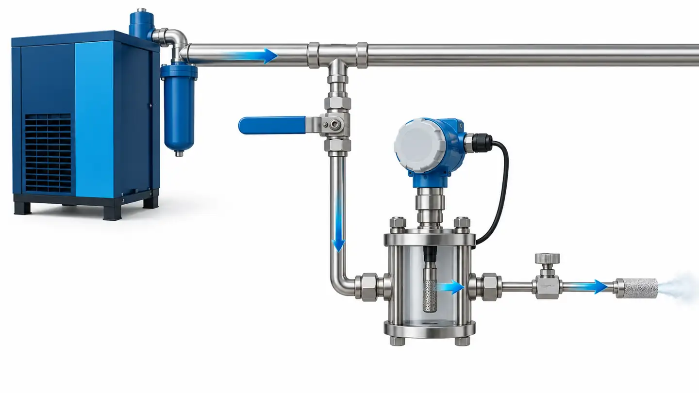
For a pressure dew-point measurement in a typical vented sample-cell arrangement, the flow restriction is downstream of the sensor. That keeps the cell close to process pressure when correctly designed and operated. Put the pressure-reducing element upstream and the probe measures the reduced-pressure sample instead. The exact assembly, allowable flow and venting method must follow the selected product's instructions; the image is a conceptual arrangement. Vaisala's installation note explains this pressure relationship and recommends controlling sample flow.
Use the shortest practical line and material appropriate to a dry-gas measurement. Some plastics and rubber can absorb water and later release it, causing long stabilization or biased low-moisture readings. Stainless-steel tubing is a common choice; the same Vaisala note explains why. Check the tubing's cleanliness, seals and pressure rating. An apparently small leak can contaminate a low-moisture sample, especially if pressure conditions allow ambient air to enter. A large chamber or long hose creates dead volume even without a leak.
Condensation in the sample path destroys representativeness: water vapor can turn to liquid before reaching the sensing element. If the sample is hot and cools through its dew point in an unheated line, the sensor no longer sees the original water-vapor content. Conversely, liquid water carried from the process can wet a sensor that is intended for vapor measurement. The Vaisala sampling note treats pressure, condensation, leaks and tubing material as part of the measurement design. A filter or conditioning system may help, but it must not remove or add water in a way that invalidates the intended quantity.
If the gas is hazardous, corrosive or expensive, venting to the room may be inappropriate. The sample-system design, exhaust handling and equipment rating then need review for that gas. A compressed-air sketch should never be reused as an installation diagram for another gas without engineering review.
Commission the whole measurement chain
An accurate probe can give a misleading process number if the sampling point, electronics or controller is wrong. Commissioning should therefore move from the physical sample to the displayed value:
- Confirm the sampling point represents the written measurement objective and that flow reaches the sensor during normal operation.
- Record gas type, line pressure, pressure at the sensor, gas temperature, sample-cell configuration and dryer operating state.
- Check line and fittings for leaks, contamination, trapped liquid and unnecessary volume.
- Let the reading stabilize after installation or after a wet upset. A fixed waiting time is weaker evidence than a stable trend under stable conditions.
- Compare the local instrument value with the control-system value. Confirm register, units, signed values, analog scaling and fault indication.
- If a calibrated portable reference is used, make sure it samples at comparable pressure and location. Two instruments with different pressure bases should not be expected to match without correction.
- Save a baseline trend and record the as-found and as-left conditions when calibration or service occurs.

Routine verification should include more than one “pass” number. Check whether the probe is physically clean and whether it recovers after a known process change. A comparison instrument must itself be in calibration and suitable for the same range. NIST's humidity metrology description illustrates why dew/frost-point calibration is tied to defined conditions and traceability; a field spot-check is a useful plausibility test but not automatically a formal calibration.
When a reading suddenly looks wetter
First determine whether the process really changed. Check the dryer status, upstream water load, regeneration state and downstream ingress. Then check sample pressure, flow, leaks, condensate, dirty filters and recent maintenance. If the transmitter is moved from a dry sample to room air and back, the recovery behavior may temporarily dominate the display. Compare the sensor with a second method or a suitably placed portable meter before resetting an alarm or changing a dryer setpoint.
When a reading looks implausibly dry
Verify that the sample has not been expanded ahead of the sensor and that the controller is not holding an old value. Look for a closed valve, dead leg, a blocked sampling path or a wrong register and unit. A reading below the transmitter's specified range is not a precise measurement simply because the display continues to count downward. Check the stated lower limit and fault output.
When two sensors disagree
Write down both pressure bases, locations, gas temperatures, technology types, calibration dates and sample-line arrangements before deciding which is wrong. An outlet transmitter and a point-of-use meter may both be correct while observing different gas. If they truly share the same sample, pressure and time interval, investigate instrument uncertainty, stabilization, contamination and signal mapping. A disagreement is a diagnostic clue, not proof that one device is defective.
A practical selection record
The following compact record turns “buy a dew-point sensor” into a testable specification. Fill in the blanks before comparing quotes:
| Field | What to record |
|---|---|
| Decision | The action driven by the value: dryer maintenance, product release, condensation prevention or reference check. |
| Moisture quantity | Dew point or frost point; any additional ppmv or RH output named separately. |
| Pressure basis | Line, sample-cell or atmospheric pressure; expected operating range and any conversion method. |
| Gas and contaminants | Air, nitrogen or other gas; oil aerosol, particles, corrosive constituents and possible liquid water. |
| Target points | Dryer outlet, distribution line, point of use, duct or chamber; reason each represents the process. |
| Required range | Normal value, alarm value and wet-upset value, all inside specified instrument limits. |
| Evidence needed | Accuracy conditions, calibration record, response/recovery data and installation manual. |
| Integration | Mechanical connection, isolation, sample flow, power, output scaling and fault handling. |
| Verification | Reference method, comparison pressure, trend interval, maintenance and recalibration plan. |
If the purpose is simply to monitor indoor comfort, a well-placed temperature/RH instrument may already answer the question. If the decision depends on very dry gas, line-pressure condensation or a formal process limit, a purpose-built dew-point transmitter or hygrometer is more likely to be justified. Choose the level of instrument by the consequence of a wrong reading, then validate the entire measurement path.
Frequently asked questions
Is dew point the same as relative humidity?
No. RH is the fraction of saturation at the gas's current temperature. Dew point is a condensation temperature for the stated pressure. One can be calculated from the other only with the needed temperature, pressure and gas assumptions. For process records, name which quantity the device actually measures and which it calculates.
Can a normal room humidity sensor measure compressed-air dew point?
It may calculate a dew point under the conditions at its own element, but that alone does not show that it can operate at compressed-air pressure, resolve the required low range or withstand the gas matrix. Use a device rated for the actual process and evaluate its complete sampling arrangement.
Where should a dew point sensor go relative to an air dryer?
To evaluate the dryer's outlet, place the measurement downstream of the dryer at a representative flowing point. To evaluate air delivered to equipment, add or move the measurement near the point of use. The best point depends on the decision; one location may not answer both questions.
Why can the value change after a pressure regulator?
Expansion changes the water-vapor partial pressure, so the sample has a different dew point at the new pressure. For pressure dew point, the sensor must be at the intended line or sample-cell pressure. Record both pressures before comparing values.
Does a low dew-point display prove ISO 8573-1 compliance?
No. ISO 8573-1 covers water as well as particle and oil purity classes. The water claim itself requires the correct quantity, location, pressure basis, measurement method and applicable class limit. A single unverified display value is not a complete compliance record.
Which technology is most accurate?
There is no single answer without a range, instrument model, gas, installation and uncertainty requirement. Chilled-mirror instruments can provide high-accuracy reference measurements under suitable conditions; metal-oxide and polymer transmitters can be strong continuous-monitoring choices within their specified envelopes. Compare actual datasheets and service needs rather than technology labels alone.
Technical sources
- Vaisala, Dew point sensing technologies and their performance differences in compressed air applications.
- Vaisala, Compressed air dew point sampling.
- Vaisala, Installing a dew point instrument into a compressed-air line.
- NIST, Hygrometers and humidity calibration services.
- ISO 8573-1:2010, Compressed air — Part 1: Contaminants and purity classes.








Leave a Reply